


") The Car Yard
The Car Yard (1047 visits) The most notable invention of latter days in bridge construction is that of the cantilever bridge, w...") View of Thomas Pope's Proposed Cantilever (1810)
View of Thomas Pope's Proposed Cantilever (1810)
The most notable invention of latter days in bridge construction is that of the cantilever bridge, which is a system devised to dispense with staging, or false works, where from the great depth, or the swift current, of the river, this would be difficult, or, as in the case of the Niagara River, impossible to make. The first design of which we have any record was that of a bridge planned by Thomas Pope, a ship carpenter of New York, who, in 1810, published a book giving his designs for an arched bridge of timber across the North River at Castle Point, of 2,400 feet span. Mr. Pope called this an arch, but his description clearly shows it to have been what we now call a cantilever. As was the fashion of the day, he indulged in a poetical description: "Like half a Rainbow rising on yon shore, While its twin partner spans the semi o'er, And makes a perfect whole that need not part Till time has furnish'd us a nobler art."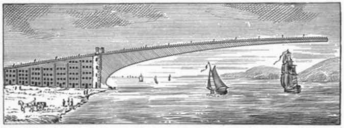
 Valleys and ravines are now crossed by viaducts of iron and steel, of which the Kinzua viaduct, illu...") Kinzua Viaduct; Erie Railway.
Kinzua Viaduct; Erie Railway.
Valleys and ravines are now crossed by viaducts of iron and steel, of which the Kinzua viaduct, illustrated here, is an example. A branch line from the Erie, connecting that system with valuable coal-fields, strikes the valley of the Kinzua, a small creek, about 15 miles southwest of Bradford, Pa. At the point suitable for crossing, this ravine is about half a mile wide and over 300 feet deep. At first it was proposed to run down and cross the creek at a low level by some of the devices heretofore illustrated in this article. But finally the engineering firm of Clarke, Reeves & Co. agreed to build the viaduct, shown above, for a much less sum than any other method of crossing would have cost. This viaduct was built in four months. It is 305 feet high and about 2,400 feet long. The skeleton piers were first erected by means of their own posts, and afterward the girders were placed by means of a travelling scaffold on the top, projecting over about 80 feet. No staging of any kind was used, nor even ladders, as the men climbed up the diagonal rods of the piers, as a cat will run up a tree.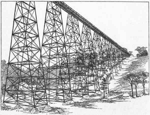
 Tunnels are neither so long nor so frequent upon American railways as upon those of Europe. The long...") Beginning a Tunnel
Beginning a Tunnel
Tunnels are neither so long nor so frequent upon American railways as upon those of Europe. The longest are from two to two and a half miles long, except one, the Hoosac, about four miles. Sometimes they are unavoidable. The ridge called Bergen Hill, west of Hoboken, N. J., is a case in point. This is pierced by the tunnels of the West Shore, of the Delaware, Lackawanna, and Western, and of the Erie, the last two of which, are placed at different levels to enable one road to pass over the other. It is by our system of using sharp curves that we avoid tunnels. It may be said, in general terms, that American engineers have shown more skill in avoiding the necessity of tunnels than could possibly be shown in constructing them. When we are obliged to use tunnels, or to make deep cuttings in rocks, our labors are greatly assisted by the use of power-drills worked by compressed air and by the use of high explosives, such as dynamite, giant powder, rend-rock, etc. Rocks can now be removed in less than half the time formerly required, when ordinary blasting-powder was used in hand-drilled holes. On the prairies of the West the road-bed is thrown up from ditches on each side, either by men with ...") Steam Excavator
Steam Excavator
On the prairies of the West the road-bed is thrown up from ditches on each side, either by men with wheelbarrows and carts, or by means of a ditching-machine, which can move 3,000 yards of earth daily. In this case the track follows immediately after the embankment, and the men live in cars fitted up as boarding-shanties, and moved forward as fast as required. After the railway line has been finally located, the next duty of the engineers is to prepare the wo...") Making an Embankment
Making an Embankment
After the railway line has been finally located, the next duty of the engineers is to prepare the work for letting. Land-plans are made, from which the right of way is secured. From the sections, the quantities are taken out. Plans of bridges and culverts are made; and a careful specification of all the works on the line is drawn up. The works are then let, either to one large contractor or to several smaller ones, and the labor of construction begins. The duties of the engineers are to stake out the work for the contractors, make monthly returns of its progress, and see that it is well done and according to the specifications and contract. The line is divided into sections, and an engineer, with his assistants, is placed in charge of each. Where the works are heavy, the contractors build shanties for their men and teams near the heavy cuttings or embankments. It is the custom to take out heavy cuttings by means of the machine called a steam shovel, which will dig as many yards in a day as 500 men. In all countries, old and new, mountainous and level, the rule should be to keep the level of track ...") Snow-sheds, Selkirk Mountains, Canadian Pacific
Snow-sheds, Selkirk Mountains, Canadian Pacific
In all countries, old and new, mountainous and level, the rule should be to keep the level of track well above the surface of the ground, in order to insure good drainage and freedom from snow-drifts. The question of avoidance of obstruction by snow is a very serious one upon the Rocky Mountain lines, and they could not be worked without the device of snow-sheds—another purely American invention. There are said to be six miles of staunchly built snow-sheds on the Canadian Pacific and sixty miles on the Central Pacific Railway. The quantity of snow falling is enormous, sometimes amounting to 250,000 cubic yards, weighing over 100,000 tons, in one slide. It is stated by the engineers of the Canadian Pacific, that the force of the air set in motion by these avalanches has mown down large trees, not struck by the snow itself. Their trunks, from one to two feet in diameter, remain, split as if struck by lightning. A full surveying party consists of the front flag-man, with his corps of axe-men to cut away trees a...") Engineers in Camp
Engineers in Camp
A full surveying party consists of the front flag-man, with his corps of axe-men to cut away trees and bushes; the transit-man, who records the distances and angles of the line, assisted by his chain-men and flag-men; and lastly the leveller, who takes and records the levels, with his rod-men and axe-men. The chief of the party exercises a general supervision over all, and is sometimes assisted by a topographer, who sketches in his book the contours of the hills and direction and size of the watercourses. One tent contains the cook, the commissary, and the provisions; another tent or two the working party, and another the superior engineers, with their drawing instruments and boards. In a properly regulated party the map and profile of the day's work should be plotted before going to bed, so as to see if all is right. If it turns out that the line can be improved and easier grades got, or other changes made, now is the time to do it. Another American invention is the switchback. By this plan the length of line required to ease the g...") A Switchback
A Switchback
Another American invention is the switchback. By this plan the length of line required to ease the gradient is obtained by running backward and forward in a zigzag course, instead of going straight up the mountain. As a full stop has to be made at the end of every piece of line, there is no danger of the train running away from its brakes. This device was first used among the hills of Pennsylvania over forty years ago, to lower coal cars down into the Nesquehoning Valley. It was afterwards used on the Callao, Lima, and Oroya Railroad in Peru, by American engineers, with extraordinary daring and skill. It was employed to carry the temporary tracks of the Cascade Division of the Northern Pacific Railroad over the "Stampede" Pass, with grades of 297 feet per mile, while a tunnel 9,850 feet long was being driven through the mountains. Equally valuable improvements were made in cars, both for passengers and freight. Instead of the fou...") A Sharp Curve—Manhattan Elevated Railway, 110th Street, New York
A Sharp Curve—Manhattan Elevated Railway, 110th Street, New York
Equally valuable improvements were made in cars, both for passengers and freight. Instead of the four-wheeled English car, which on a rough track dances along on three wheels, we owe to Ross Winans, of Baltimore, the application of a pair of four-wheeled swivelling trucks, one under each end of the car, thus enabling it to accommodate itself to the inequalities of a rough track and to follow its locomotive around the sharpest curves. There are, on our main lines, curves of less than 300 feet radius, while, on the Manhattan Elevated, the largest passenger traffic in the world is conducted around curves of less than 100 feet radius. There are few curves of less than 1,000 feet radius on European railways.") Locomotive of To-day
Locomotive of To-day") Rail Making
Rail Making") The Last Span - ready to join
The Last Span - ready to join The farmer sells his crop of wheat to the grain-dealer, and carts it, say, to Brandon, where the pur...") C. P. R. grain elevator at Fort William, Ontario
C. P. R. grain elevator at Fort William, Ontario
The farmer sells his crop of wheat to the grain-dealer, and carts it, say, to Brandon, where the purchaser takes delivery of it at his elevator. Let us examine this thing somewhat minutely, taking by way of illustration one of the elevators belonging to the Canadian Pacific Railway Company at Montreal. It is a medium-sized one, having capacity for storing about 600,000 bushels of grain. The same company’s elevators at Fort William and Port Arthur are much larger, having capacity for 1,500,000 bushels. In Chicago and Buffalo there are elevators of three millions of bushels capacity; but, whether larger or smaller, in their main features they are all alike. The elevator is a wooden structure of great strength. Its massive stone foundations rest on piles imbedded in concrete. The framework is so thoroughly braced and bolted together as to give it the rigidity of a solid cube, enabling it to resist the enormous pressure to which it is subjected when filled with 18,000 tons of wheat. The building is 210 feet long, 80 feet wide, and 142 feet in height from basement to the peak of the roof. Including the steam-engine (built at the C. P. R. works) of 240 horse-power, the entire cost of this elevator was $150,000. It consists of three distinct compartments—for receiving, storing, and delivering grain. On the ground floor are two lines of rails by which the cars have ingress and egress. The general appearance of this flat is that of a bewildering array of ponderous posts and beams, shafting, cog-wheels, pulleys and belts, blocks and tackle, chutes, and the windlasses for hauling in and out the cars, for a locomotive with its dangerous sparks may not cross the threshold. Beneath this, in the basement, are the receiving tanks, thirty-five feet apart from centre to centre, corresponding to the length of the cars. Of these there are nine, enabling that number of cars to be simultaneously unloaded. This is quickly done by a shovel worked by machinery, with the aid of two men, the grain falling through an iron grating in the floor into the tank. The elevator has nine “legs.” The leg is an upright box, 12 inches by 24 inches, extending from the bottom of the tank to the top of the building; inside of it is a revolving belt with buckets attached 15½ inches apart. The belt is 256 feet long, and as it makes 36 revolutions per minute, each bucket containing one-third of a bushel, each leg is able to raise 5,250 bushels per hour. A car is unloaded and its contents hoisted into the upper regions in fifteen minutes. When all the legs are at work 30,000 bushels are handled in an hour. The Forth Bridge at the Present Day.
Building the Bridge. ...") The Forth Bridge
The Forth Bridge
The Forth Bridge at the Present Day. Building the Bridge. Train crossing the Bridge. The mouth of the Forth has very nearly bitten Scotland in two, and anybody who wishes to travel from Edinburgh to Dunfermline would have to go a long way round if they objected to crossing the river. Formerly a great many people did object to this, because they knew that, although the voyage was only about a short mile, the great billows from the North Sea would meet them before it was over, and give them a very unpleasant time. So everybody who had anything to do with the Forth was willing that it should be spanned by a reliable bridge, and plans for carrying this into effect were frequently proposed. Indeed, arrangements were almost completed in 1879 for building a huge suspension bridge from shore to shore. The drawings were made, the estimates prepared, and the spades and trowels even beginning to work on the foundations, when, one sad December night, a terrible gale arose. All through the hours of darkness it roared and shrieked across the British Isles, working havoc upon sea and land, but, when morning came at last, few were prepared for the appalling catastrophe it had caused. Sweeping up the Firth of Tay, it had torn away a portion of the great railway bridge that crossed the inlet, and hurled it into the water. A train was passing over at the time, and plunged into the abyss with all its passengers. The terrible event shook public confidence, and we might almost say that the gale of that December night caught all the drawings and papers connected with the proposed suspension bridge over the Forth, and swept them from public favour. Immediately afterwards, Sir John Fowler and Mr. Benjamin Baker (both celebrated engineers) came forward with an alternative plan of which no one could doubt the strength. It may perhaps be described as an arch-suspension bridge, because the design includes the strength of both styles; but engineers themselves call it a cantilever bridge. It was called the 'Locomotion.' George Stephenson stood ready to drive it as soon as the trucks, whi...") The first Railway Journey in England
The first Railway Journey in England
It was called the 'Locomotion.' George Stephenson stood ready to drive it as soon as the trucks, which a stationary engine was lowering down the slope by means of a wire rope, had been attached to it. In the first of these trucks came the Directors of the Railway Company and their friends, followed by twenty-one trucks (all open to the sky, like ordinary goods-trucks), loaded with various passengers, and finally six more waggons of coal. Such was the first train. A man on horseback, carrying a flag, having taken up his position in front of the 'Locomotion' to head the procession, the starting word was given, and with a hiss of steam, half drowned in the shouting of the crowd, the first railway journey ever made in England was begun. While in Paris, President Yerkes, of the North Chicago Street Railway Company, purchased a noiseless...") A Steam Street Railway Motor
A Steam Street Railway Motor
While in Paris, President Yerkes, of the North Chicago Street Railway Company, purchased a noiseless steam motor, the results in experimenting with which will be watched with great interest. The accompanying engraving, for which we are indebted to the Street Railway Review, gives a very accurate idea of the general external appearance. The car is all steel throughout, except windows, doors, and ceiling. It is 12 ft. long, 8 ft. wide, and 9 ft. high, and weighs about seven tons. The engines, which have 25 horsepower and are of the double cylinder pattern, are below the floor and connected directly to the wheels. The wheels are four in number and 31 in. in diameter. The internal appearance and general arrangement of machinery, etc., is about that of the ordinary steam dummy. It will run in either direction, and the exhaust steam is run through a series of mufflers which suppress the sound, condense the steam and return the water to the boiler, which occupies the center of the car. The motor was built in Ghent, Belgium, and cost about $5,000, custom house duties amounting to about $2,000 more. In some English and Scotch mines, and also in some of the French mines, where the seams of coal are ...") Sections of an English Coal Mine
Sections of an English Coal Mine
In some English and Scotch mines, and also in some of the French mines, where the seams of coal are thin, boys, who are called “putters,” are employed to draw small carts along a railway. They fasten themselves to the cart with belts around their waists, and draw it along, going sometimes on their hands and feet where the road is wet and rough. Sometimes one of them pulls the cart while the other pushes it. In some of the Scotch mines girls formerly performed this work; but of late the laws do not allow women to work under ground. Girls used to carry on their backs a basket fastened to a leather strap which passed around their foreheads. A lamp was attached to the strap, and in this way they carried their loads up the long ladders and through the inclines, sometimes a distance of several hundred feet. If a strap broke, a block of coal fell, or a bearer missed her footing, those below were seriously hurt, and many fatal accidents occurred. This primitive mode of raising coal was abolished by law. The owners of the mines had become so careless in regard to the management of their laborers that the government was obliged to interfere. Rear elevation of Pioneer and detail of valve shifter; valve face and valve. (Drawing by J. H. White...") Rear elevation of Pioneer
Rear elevation of Pioneer
Rear elevation of Pioneer and detail of valve shifter; valve face and valve. (Drawing by J. H. White.) Diagram comparing the Pioneer (shaded drawing) with the Columbia, a standard 8-wheel engine of 1851....") Diagram comparing the Pioneer with the Columbia
Diagram comparing the Pioneer with the Columbia
Diagram comparing the Pioneer (shaded drawing) with the Columbia, a standard 8-wheel engine of 1851. (Drawing by J. H. White.) Columbia Hudson River Railroad Lowell Machine Shop, 1852 Wt. 271/2 tons (engine only) Cyl. 161/2 x 22 inches Wheel diam. 84 inches Pioneer Cumberland Valley Railroad Seth Wilmarth, 1851 121/2 tons 81/2 x 14 inches 54 inches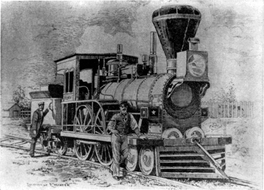 The Fury
The “Fury,” built for the Boston and Worcester Railroad in 1849 by Wilmarth. It was known as a “Shanghai” because of its great height. “Pioneer” locomotive. (Drawing by J. H. White.)") Pioneer Locomotive
Pioneer Locomotive
“Pioneer” locomotive. (Drawing by J. H. White.) “Pioneer” locomotive,
(1) Safety valve,
(2) spring balance,
(3) steam jet
(4) dry pipe
(5...") Pioneer Locomotive
Pioneer Locomotive
“Pioneer” locomotive, (1) Safety valve, (2) spring balance, (3) steam jet (4) dry pipe (5) throttle lever (6) throttle (7) crown bar (8) front tube sheet (9) check valve (10) top rail (11) rear-boiler bracket (12) pedestal (13) rocker bearing (14) damper (15) grate (16) bottom rail (17) pump heater valve (18) cylinder lubricator (19) reversing lever (20) brake shoe (21) mud ring (22) blowoff cock (23) ashpan (Drawing by J. H. White.)
Patent Iron Suspension Railroad Bridge.
The undersigned would inform the officers of Railroads ...") Wendell Bollmans Patent Bridge
Wendell Bollmans Patent Bridge
Patent Iron Suspension Railroad Bridge. The undersigned would inform the officers of Railroads and others, that he is prepared to furnish Drawings and Estimates for Bridges, Roofs, etc., on the plan of Bollman’s Patent. The performance of these bridges, some of which have been in use for six years, has given entire satisfaction. Their simplicity of construction renders repairs easy and cheap, and by a peculiar connection of the Main and Panel Rods at the bottom of the Posts, all danger from the effects of expansion, which has heretofore been the chief objection to Iron Bridges, is entirely removed. J. H. TEGMEYER, Baltimore, Md. Shortly after the Harpers Ferry bridge reconstruction, Bollman was made foreman of bridges. It is ap...") Plan of Harpers Ferry Bridge
Plan of Harpers Ferry Bridge
Shortly after the Harpers Ferry bridge reconstruction, Bollman was made foreman of bridges. It is apparent that, on the basis of his practical ability, enhanced by the theoretical knowledge gained by intense self-study, he eventually came to assist Chief Engineer Benjamin H. Latrobe in bridge design. He later took this work over entirely as Latrobe’s attentions and talents were demanded in the location and extension of the line between Cumberland and Wheeling. In 1830 all this had disappeared, and we find in Mr. Nasmyth's sketch a regular fire-box, such as is...") The Rocket 1830
The Rocket 1830
In 1830 all this had disappeared, and we find in Mr. Nasmyth's sketch a regular fire-box, such as is used to this moment. In one word, the Rocket of 1829 is different from the Rocket of 1830 in almost every conceivable respect; and we are driven perforce to the conclusion that the Rocket of 1829 never worked at all on the Liverpool and Manchester Railway; the engine of 1830 was an entirely new engine. a, a, a, tuyères; b, air-space; c, melted metal
A very important development of the manufacture ...") Bessemer Converting Vessel
Bessemer Converting Vessel
a, a, a, tuyères; b, air-space; c, melted metal A very important development of the manufacture of steel followed the introduction of the 'Bessemer process,' by means of which a low carbon or mild cast-steel can be produced at about one-tenth of the cost of crucible steel. It is used for rails, for the tires of the wheels of railway carriages, for ship-plates, boiler-plates, for shafting, and a multitude of constructional and other purposes to which only wrought iron was formerly applied, besides many for which no metal at all was used.