


 showing the large size of the elevators, the position of the pilot, and the placing of the propeller...") The Cody Biplane from above
The Cody Biplane from above
showing the large size of the elevators, the position of the pilot, and the placing of the propellers. A.A. Ballast bags filled with sand
B. Instruments (such as a statoscope, which shows at any moment ...") The car of a modern Balloon
The car of a modern Balloon
A.A. Ballast bags filled with sand B. Instruments (such as a statoscope, which shows at any moment whether the balloon is rising or falling; and an altitude meter) C. Ring by which car is attached to balloon. Hence there is a type of fast scouting monoplane, in which a pilot can ascend alone, and fly at 100 ...") Single-seated Air Scout
Single-seated Air Scout
Hence there is a type of fast scouting monoplane, in which a pilot can ascend alone, and fly at 100 miles an hour. With such a craft, sweeping rapidly above an enemy’s position, the pilot-observer can return with his information at surprising speed. In the figure an air-scout of this type is seen. The tapering, covered-in body will be observed; this is to reduce wind resistance as the machine rushes through the air. The Gnome engine is, for the same reason, covered by an aluminium shield, which only allows the lower cylinders to project; they must, of course, be exposed in some way to the air, or they would not cool themselves. The landing-carriage has been reduced to its simplest form; this, again, is to reduce wind resistance; and the pilot, sitting deep in the body, shows only his head as the machine flies. Here, again, apart from the greater comfort in being so shielded, the placing of the pilot within the machine spells a lessening of pressure. A. Propeller B. Motor (partly hidden by shield) C. Pilot’s seat D. Sustaining plane E. Rudder F. Elevating-plane G. Chassis. But as airships were built larger, and greater speeds were obtained, it became necessary to strength...") Semi-rigid Airship
Semi-rigid Airship
But as airships were built larger, and greater speeds were obtained, it became necessary to strengthen the envelopes with some form of keel; and this led to a type which is known as the semi-rigid, and is developed successfully in France. The figure illustrates an airship of this build. Along the lower side of its envelope is placed a light, rigid framework or keel, and from this is suspended the car which contains engines and crew. A. Gas-containing envelope B. Strengthening keel C.C. Stabilising-planes D. Rudder E. Car carrying engines, propeller, and crew. A coastal sea-plane, as now planned, is a craft having, say, two engines, each devolving 120 h.p., w...") Sea-plane to carry a crew of seven
Sea-plane to carry a crew of seven
A coastal sea-plane, as now planned, is a craft having, say, two engines, each devolving 120 h.p., with a wing span of some 80 feet, and an accommodation in its hull for three men—the pilot, a combatant with a machine-gun, and an observer with an installation of wireless. But types are changing constantly, and the tendency is to build larger craft. A machine weighing a couple of tons is shown, and a novelty in regard to it is that it has wheels upon either side of its boat-shaped car, upon which it can move on land, and which fold upward when it rests upon the water. A. Hull upon which the machine floats when in the sea B.B.B. Wheels upon which it may move when on land, and which fold upward when it is on the water C. Pilot’s controlling wheel D.D. Main sustaining planes E. Four-bladed propeller driven by chain-gearing from engine within the hull. To meet the demand for a purely scouting machine, in which pilot and passenger shall have a clear fi...") Scouting Monoplane, with occupants below the wings.
Scouting Monoplane, with occupants below the wings.
To meet the demand for a purely scouting machine, in which pilot and passenger shall have a clear field for observation, both above and below, a monoplane has been designed which is called the “parasol.” This machine, a Morane-Saulnier, is shown. The two sustaining wings, forming a single surface, are raised above the body so that its occupants have nothing to impede their view earthward; and they can also see above them—an advantage of course in time of war, seeing that an enemy might be hovering overhead A. Engine and propeller B. Plane raised above hull C. Seats for pilot and passenger D. Rudder E. Elevating-plane. When petrol engines became available, they gave an impetus to the building of airships; for, like th...") Santos-Dumont’s Airship
Santos-Dumont’s Airship
When petrol engines became available, they gave an impetus to the building of airships; for, like the aeroplane, the airship needed a motive agent which gives a high power for a low weight. One of the first to use a petrol motor in an airship with success was M. Santos-Dumont, whose name has been mentioned in connection with aeroplanes. He tested small, light airships, driven by petrol engines and two-bladed propellers—as illustrated in figure; and with one of these, on a calm, still day, he flew over Paris and round the Eiffel Tower. A. Gas envelope B. Wheeled framework which carried motor, propeller, and pilot’s seat C. Elevating-plane D. Horizontal rear-plane E. Rudder. The fitting of several motors has been shown to be practical; and it has the obvious advantage that,...") Multiple-engined craft
Multiple-engined craft
The fitting of several motors has been shown to be practical; and it has the obvious advantage that, should one fail while in the air, the other or others will maintain a craft in flight. In such a machine as would fly the Atlantic, for example, it is proposed to fit four motors developing 800 h.p., and to carry a couple of mechanics who would constantly be tending them. Thus, should one engine develop trouble, its repair could be effected without descent, and with no worse result than a temporary fall in speed. In the figure is shown a method by which three Gnome motors may be fitted to a biplane. A. First engine (a 50-h.p. Gnome) B. Second engine (which is on the same shaft, but will run independently) C. Third Gnome engine, also an independent unit D. Four-bladed propeller (mounted higher than the crank-shaft bearing the engines, and driven by a chain gearing). (Early Type)
A. Elevating-plane
B. Seats for pilot and passenger
C. Main-planes
D. Motor with...") Maurice Farman Biplane
Maurice Farman Biplane
(Early Type) A. Elevating-plane B. Seats for pilot and passenger C. Main-planes D. Motor with two-bladed propeller E. Vertical panel F. Aileron G. Tail-planes H. Rudders I. Landing chassis. “Looping the loop,” which has made so great a sensation, has taught airmen one definite lesson; ...") Looping the loop
Looping the loop
“Looping the loop,” which has made so great a sensation, has taught airmen one definite lesson; and it is this: no matter how their machines may be beaten and tossed by the wind, they need not fear a fall—provided they are high enough above ground. The movements of a machine, as it makes a series of “loops,” are shown in the figure. The pilot reaches a high speed before he rears up his machine to begin the “loop,” and this downward velocity is attained by diving; then, when he estimates his pace sufficient, he pulls his elevating-lever back and the machine leaps upward, rearing itself vertically towards the sky, turning over on its back, then diving again and coming right-side-up—thus achieving a complete somersault. A skilled trick-flyer, also, will allow his machine to drop sideways or tail first, deliberately working the controls so that it shall do so. Then, just as it seems to spectators that he is falling to destruction, he will dive or twist, regain the mastery of his machine, and descend in a normal glide. There is a type of aeroplane which will be carried to sea when a fleet sails, stowed in sections wit...") Launching sea-planes from a ship’s deck
Launching sea-planes from a ship’s deck
There is a type of aeroplane which will be carried to sea when a fleet sails, stowed in sections within the hull of a transport ship. This machine—a light, high-speed craft—will be assembled upon the deck of its parent ship, and launched into the air by special mechanism, as there is not room for a machine to run upon wheels, and leave the ship’s deck as it might do upon land; the vessel, besides, might be rolling in a high sea. In some cases a platform is built upon the deck, either at the bow or stern, and along this the aircraft moves, so as to gain speed for its planes to lift. In one device, seen in Figure, the machine is mounted upon a light wheeled cradle, and this is placed upon the starting-rail. Then, driven by its propeller, the plane runs forward upon the cradle till it reaches the end of the rail, when it glides into the air, the cradle falling from it and dropping into the sea, from which it is retrieved and drawn back on board the ship. The sea-plane (A.) is seen taking flight, having glided upon its cradle along the platform (B.). The cradle (C.) is just falling away below the aircraft’s hull. By another method, shown in figure, the sea-plane is launched from a cable suspended between two mas...") Launching a sea-plane from a wire
Launching a sea-plane from a wire
By another method, shown in figure, the sea-plane is launched from a cable suspended between two masts, and can come to rest upon the cable again after a flight has been made. The machine is hung upon the cable prior to making an ascent; then the pilot starts his engine, and as his machine glides forward along the cable he releases a catch and soars into the air. Upon returning he flies beneath the cable, and makes his craft rise until the “V”-shaped apparatus above his head is caught by the cable and the catch becomes operative; then he stops his motor, and his craft hangs from the cable as it did before. A. Sea-plane B. Cable C. The “V”-shaped apparatus which guides the cable into the clip (D.) and so suspends the machine from the wire. Hull of a Zeppelin during construction.
Craft of the semi-rigid type provide a link between small...") Hull of a Zeppelin during construction
Hull of a Zeppelin during construction
Hull of a Zeppelin during construction. Craft of the semi-rigid type provide a link between small, non-rigid ships and the very large machine which is built with an entirely rigid framework, and has its example in the Zeppelin. The maker forms a skeleton hull of aluminium or some light metal alloy, a method that is shown in figure. The hull of a Zeppelin, slightly more than 500 feet in length, is sheathed with tightly stretched fabric; and within it are the gas-containers—a row of seventeen separate balloons, each in a compartment by itself, and containing a total of nearly 1,000,000 cubic feet of gas—which give these airships a lifting power of close upon 30 tons. showing shape and spread of planes and tail, and position of pilot and passenger.") Grahame-White Military Biplane
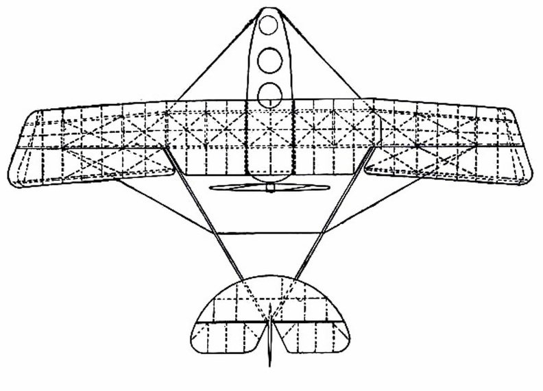
Grahame-White Military Biplane
showing shape and spread of planes and tail, and position of pilot and passenger.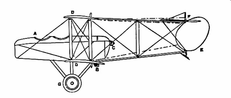
 Once the value of aerial reconnaissance had been proved, France proceeded to the development of a sc...") Grahame-White Military Biplane - side view
Grahame-White Military Biplane - side view
Once the value of aerial reconnaissance had been proved, France proceeded to the development of a scouting aeroplane; and the need, in such a machine, is that the observer shall have a clear view ahead and below. The construction of machines was, for this reason, modified. The front elevating plane was moved to the rear, where it was fitted in the form of a flap—as in the case of monoplanes—and the pilot and observer placed in a covered-in body, which projected in front of the main-planes, as shown in the figure. By placing the body before the planes, the observer has a clear view ahead and on either side; and even when he leans over the side, and looks directly downward, there is no surface to obstruct him. A. Covered-in body, with seats for pilot and passenger B. Motor (to minimise wind resistance, only the lower cylinders are exposed to the air) C. Propeller D. Main-planes E. Rudder F. Elevator G. Landing gear.
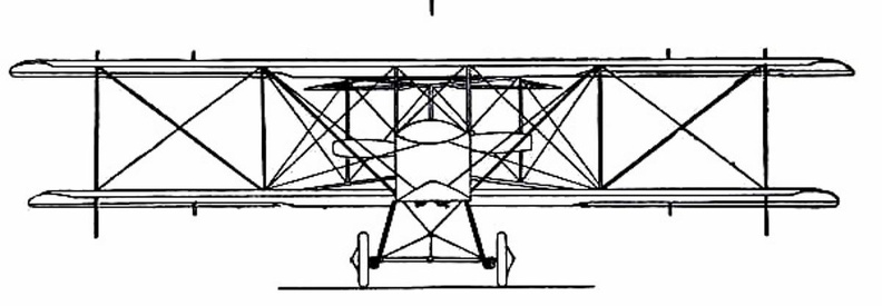
 showing the position of the body and the construction of the landing gear.") Grahame-White Military Biplane - front view
Grahame-White Military Biplane - front view
showing the position of the body and the construction of the landing gear.
 A typical craft, representing the first of those navigated with any certainty, is shown in Figure. A...") Early-type Airship
Early-type Airship
A typical craft, representing the first of those navigated with any certainty, is shown in Figure. A gas-containing envelope, made of a light, strong, varnished fabric, is kept taut by the pressure of the gas within; the car, constructed of wood or metal tubing, is suspended by ropes from the envelope, and contains engine and crew, with a two-bladed propeller revolving astern. Such a machine, in its control, had an elevating-plane and rudder, upon the same principle as those of the aeroplane. One of the difficulties to be overcome was the expansion and contraction of gas in the envelope owing to differences in altitude and temperature. When the craft ascended, its envelope completely inflated, the gas began to dilate owing to the outer air becoming less dense; and some had to be allowed to escape through automatic valves. Then, should the machine descend to a lower level, there was not sufficient gas in the envelope to keep it tightly stretched, and it tended to sag at the bow as it was driven through the air. A. Gas envelope B. Car suspended below envelope C. Motor, which drives propeller (D) through a shaft E. Small horizontal plane for rising or descending F. Fixed fin, or keel plane, to give stability G. Rudder. Another machine which is stable in flight, owing to the peculiar formation of its wings, which resis...") Dunne inherently stable Biplane
Dunne inherently stable Biplane
Another machine which is stable in flight, owing to the peculiar formation of its wings, which resist a diving or plunging movement, or a lateral swing, is the Dunne biplane—as designed by Lieutenant J. W. Dunne. This craft is seen in the figure. Using such a machine, pilots have flown for long distances with the control levers locked, the biplane adapting itself automatically to the wind-gusts and preserving its equilibrium without aid of any kind. It has neither fore-plane nor tail; it is made to ascend by elevators which are in the form of hinged flaps, or ailerons, and is steered by two rudders at the extremities of the main-planes. A. Hull containing pilot and passenger B.B. Main-planes C.C.C.C. Flaps used as elevators D.D. Side-planes which act as rudders E. Engine and propeller F. Alighting gear.") Driving-seat of a touring plane
Driving-seat of a touring plane Biplane (548 visits) A. Hull, which is steel-built, containing pilot and passenger
B. Main-planes—the lower at a dihed...") D.F.W. (German-designed) Biplane
D.F.W. (German-designed) Biplane
A. Hull, which is steel-built, containing pilot and passenger B. Main-planes—the lower at a dihedral angle C. Uptilted stabilising ailerons, which may be locked in position D. Stabilising fin E. Rudder F. Elevating-plane G. 100-h.p. motor (which is enclosed) and propeller. A. Wheels operating elevating-planes and rudder
B. Height recorder
C. Speaking-tube to communicate...") Control platform of an Airship
Control platform of an Airship
A. Wheels operating elevating-planes and rudder B. Height recorder C. Speaking-tube to communicate with engineers. A. Lower part of aeroplane’s hull
B. Revolving barrel to which bombs are clipped
C. Bombs
D. Re...") Bomb-releasing mechanism
Bomb-releasing mechanism
A. Lower part of aeroplane’s hull B. Revolving barrel to which bombs are clipped C. Bombs D. Releasing mechanism operated by marksman in machine. Bombs may be carried and dropped when opportunity offers; and as an improvement upon the early method, which was simply to throw these from the machine, there are releasing mechanisms now devised which carry a number of projectiles and drop them one by one as a lever is moved. The bombs, which are long, pointed, and balanced so that they will fall head first, are clipped round a barrel rather like that of a revolver, which is fixed beneath the aeroplane’s hull just below the occupants’ seat. Mechanism causes the carrying chamber to revolve and bring each bomb against a releasing catch, which—at a movement of the marksman’s lever—throws it outwards and downward. Coal-gas superseded hot air in the filling of balloons, the latter being unsatisfactory, seeing that...") A modern Balloon
A modern Balloon
Coal-gas superseded hot air in the filling of balloons, the latter being unsatisfactory, seeing that it cooled rapidly and allowed the balloon to descend; the only alternative being to do what some of the first aeronauts did, and burn a fire below the neck of their balloon even when in the air. But the dangers of this were great, seeing that the whole envelope might easily become ignited. With balloons filled with coal-gas long flights were possible, but they had always this disadvantage—the voyagers were at the mercy of the wind, and could not fly in any direction they might choose. If the wind blew from the north then they were driven south, the balloon being a bubble in the air, wafted by every gust. Aeronauts became disgusted with this inability to guide the flight of a balloon, and many quaint controls were tested; such, for example, as the use of a large pair of oars with which the balloonist, sitting in the car of his craft, rowed vigorously in the air. showing the span of the main-planes, and the curve of the boat-shaped hull.") A Flying Boat
A Flying Boat
showing the span of the main-planes, and the curve of the boat-shaped hull.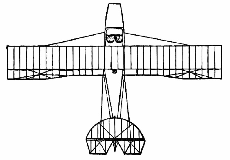
 showing the shape of wings and tail, and the positions of the pilot and passenger within the hull.
...") A Flying Boat top view
A Flying Boat top view
showing the shape of wings and tail, and the positions of the pilot and passenger within the hull.
 A. Hull
B. seats for crew
C. Planes
D. Motor
E. Propeller
F. Rudder
G. Elevators.
...") A Flying Boat - side view
A Flying Boat - side view
A. Hull B. seats for crew C. Planes D. Motor E. Propeller F. Rudder G. Elevators.
 England, in the building and handling of sea-planes has come well to the fore, and our machines are ...") A Bleriot Sea-plane
A Bleriot Sea-plane
England, in the building and handling of sea-planes has come well to the fore, and our machines are more advanced than those of other countries. The Admiralty has recognised that, acting as a coastal scout in time of war, such craft would be of the utmost value; thus we find air-stations dotted round our seaboard, from which machines may fly in a regular patrol. By the employment of hundreds of craft, operating upon a well-ordered plan, it will be possible in the future to girdle our shores completely; and such machines would not only spy out the approach of an enemy’s fleet, but give battle to hostile aeroplanes or airships which might seek to pass inland. The type of machine we have just described was a biplane, but there are monoplane sea-craft, and a Bleriot fitted for alighting upon the water is shown. ...it was followed in due course by the use of small steam engines and electric motors, which were ...") An Experimental Airship
An Experimental Airship
...it was followed in due course by the use of small steam engines and electric motors, which were made to turn propellers such as are used in aeroplanes. For such experimental craft, the rounded form of gas-container was abandoned and a cigar-shaped envelope adopted, pointed at both ends, which could be more easily driven through the air. An airship of a crude and early type is seen here. It was built by an experimenter named Gifford, and in 1852 it flew at the rate of seven miles an hour. A. Gas-containing envelope; B. Car suspended below envelope, which carried the aeronaut and a 3-horse-power steam engine; C. Two-bladed propeller driven by the engine; D. Rudder (in the form of a sail) by which the machine could be steered from side to side. The sea-plane, when a flight is made, is launched upon the water down a slipway; then the pilot and ...") An Avro Sea-Plane
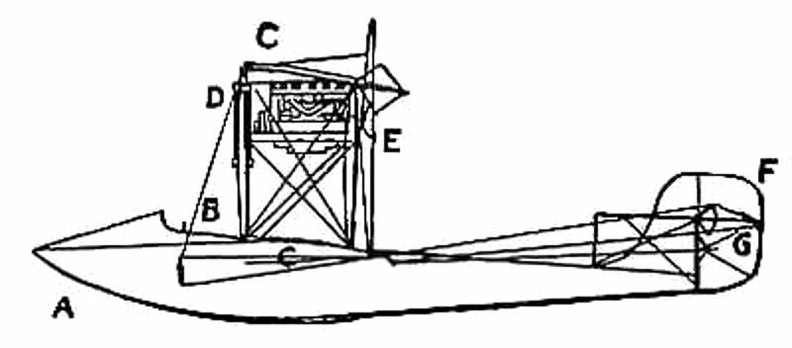
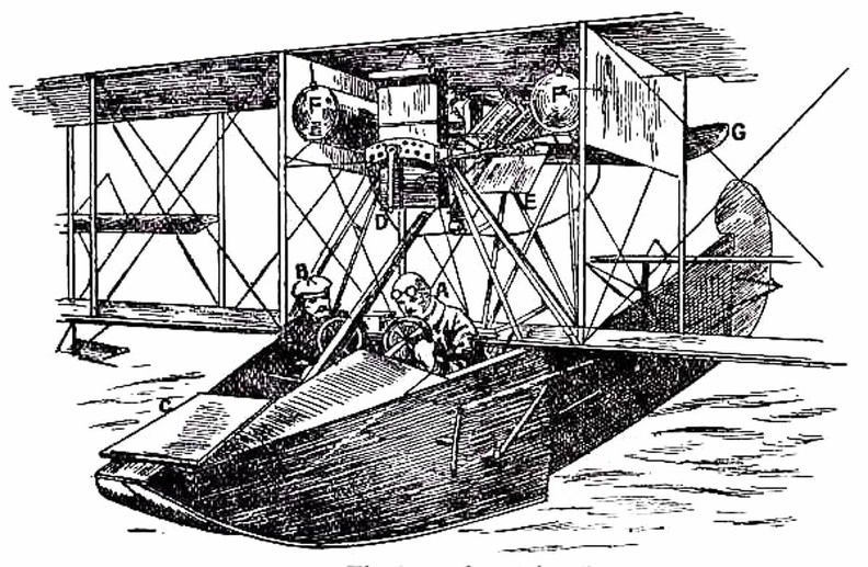
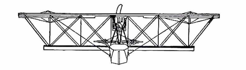
An Avro Sea-Plane
The sea-plane, when a flight is made, is launched upon the water down a slipway; then the pilot and his passenger embark, the motor is started, and the propeller draws the machine across the water at a rapidly increasing pace. The floats raise themselves higher and higher upon the water, as the air-planes exercise a growing lift, until they only just skim the surface. And now comes the moment when the airman, drawing back his elevating lever, seeks to raise his craft from the water into the air. At first only the front of the floats rise, the rear sections clinging to the surface; then, in another instant, the whole float frees itself from the water in a scatter of spray, and the craft glides at a gently-sloping angle into the air. It is the aim of builders, by the curve they impart, to make the floats leave the water with as little resistance as possible. In the floats of the Avro will be noticed a notch, or cut-away section, which occurs at about the centre of the float upon its lower side. This is called a “step,” and is to help the float to lift from the water. When the main-planes draw upward, as the craft moves prior to its flight, the floats tend, as has been said, to raise themselves in the water; and as they do so, lifting first towards the bow, there comes a space between the upward-cut “step” and the surface of the water. Into this space air finds its way and, by helping still further to free the float from the surface, aids greatly at the moment when the pilot—operating his hand-lever—seeks the final lift which will carry him aloft. A. Propeller B. 100-h.p. Gnome motor, hidden by shield C. Main-planes D. Observer’s seat E. Pilot’s seat F. Rudder G. Elevating-plane H. Float to support tail I. Main floats to bear the weight of the machine. An Airship leaving its shed
A. The machine emerging stern first
B. A sister craft in dock
C. Th...") An Airship leaving its shed
An Airship leaving its shed
An Airship leaving its shed A. The machine emerging stern first B. A sister craft in dock C. The launching crews D. Rails upon which the cars of the airship move, so as to prevent its swinging sideways in a gust E. Outlook station upon the roof of the shed F. Workshops; living quarters for the crews; plant for making hydrogen gas. Airships, like aeroplanes, are being armed with guns and bombs; and their power of raising weights e...") Aeroplanes attacking an airship from above
Aeroplanes attacking an airship from above
Airships, like aeroplanes, are being armed with guns and bombs; and their power of raising weights enables them to carry heavy weapons. Large and highly destructive bombs have been tested in the German airships, being released over the sea and aimed at targets in the form of rafts. Latest-type airships also carry guns in their cars; and the Zeppelins have a platform upon the tops of their hulls, reached by a ladder through the middle of the ship, from which a machine-gun can be fired upward. This is a very necessary precaution, and is intended to frustrate the attack of an aeroplane. It would be the aim of the latter, whenever possible, to manœuvre above its big enemy—as suggested in figure —and drop a bomb upon its hull. Hence the construction of the top platform of the airship, from which her gunners can direct a vigorous fire aloft. Air-racing, as made popular by the proprietors of the Hendon aerodrome, forms so fascinating a sight...") A pylon, or mark-tower, on the flying track
A pylon, or mark-tower, on the flying track
Air-racing, as made popular by the proprietors of the Hendon aerodrome, forms so fascinating a sight that, on a day of public holiday, as many as 50,000 people will assemble in the enclosures. To stand near one of the pylons—wooden towers which mark the turning-points of the course—and see the air-racers come rushing by, is to gain such an impression of speed as almost makes the watcher hold his breath. The pilot in a flying race has one chief aim: to fly the shortest way. Every fraction of a second is of importance; and if he can circle the pylons more skilfully than his rivals, he may win the race, even though his machine—in its actual speed—may be no faster than theirs. The Simuliidæ, or black flies, are small, dark, or black flies, with a stout body and a hump-back a...") Simulium venustum
Simulium venustum
The Simuliidæ, or black flies, are small, dark, or black flies, with a stout body and a hump-back appearance. The antennæ are short but eleven-segmented, the wings broad, without scales or hairs, and with the anterior veins stout but the others very weak. The mouth-parts are fitted for biting. Sepsis violacea; puparium and adult") Sepsis violacea; puparium and adult
Sepsis violacea; puparium and adult
Sepsis violacea; puparium and adult") Section through a venom gland of Latrodectus 13-guttatus showing the peritoneal, muscular and epithelial layers
Section through a venom gland of Latrodectus 13-guttatus showing the peritoneal, muscular and epithelial layers") Sarcoptes scabiei. Diagrammatic representation of the course in the skin of man
Sarcoptes scabiei. Diagrammatic representation of the course in the skin of man") Sarcoptes scabiei, male
Sarcoptes scabiei, male") Sarcoptes scabiei, female
Sarcoptes scabiei, female") Salivary glands of Notonecta maculata
Salivary glands of Notonecta maculata personatus (601 visits)") Reduvius (Opsicœtus) personatus
Reduvius (Opsicœtus) personatus") Rasahus biguttatus
Rasahus biguttatus") Poison apparatus of a honey bee
Poison apparatus of a honey bee") Piophila casei
Piophila casei containing the mouth parts (a) beneath the alimentary canal (p) (646 visits)") Pediculus showing the blind sac (b) containing the mouth parts (a) beneath the alimentary canal (p)
Pediculus showing the blind sac (b) containing the mouth parts (a) beneath the alimentary canal (p)") Pediculoides ventricosus, female
Pediculoides ventricosus, female megnini, male. (a) dorsal, (b) ventral aspect (604 visits)") Otiobius (Ornithodoros) megnini, male. (a) dorsal, (b) ventral aspect
Otiobius (Ornithodoros) megnini, male. (a) dorsal, (b) ventral aspect megnini, head of nymph (698 visits)") Otiobius (Ornithodoros) megnini, head of nymph
Otiobius (Ornithodoros) megnini, head of nymph") Notœdres cati, male and female
Notœdres cati, male and female") Muscina stabulan
Muscina stabulan") Mandible of Scolopendra cingulata showing venom gland
Mandible of Scolopendra cingulata showing venom gland") Lucilia cæsar
Lucilia cæsar larva; (enlarged). (b) adult; (natural size) (583 visits)") Linguatula. (a) larva; (enlarged). (b) adult; (natural size)
Linguatula. (a) larva; (enlarged). (b) adult; (natural size)") Life cycle of the malarial parasite
Life cycle of the malarial parasite") Left spiracle of nymph of Argas persicus
Left spiracle of nymph of Argas persicus") Left hand stigmata of the larvæ of muscoidea
Left hand stigmata of the larvæ of muscoidea") Larva of Simulium
Larva of Simulium") Larva of Fannia scalaris
Larva of Fannia scalaris") Larva of Anopheles
Larva of Anopheles") Ixodes ricinus; male, ventral aspect
Ixodes ricinus; male, ventral aspect and its relation to the chelicera (a) (576 visits)") Head of a spider showing poison gland (c) and its relation to the chelicera (a)
Head of a spider showing poison gland (c) and its relation to the chelicera (a)