


Accueil / Albums / Technology / Transport 641

 In 1850 a clockmaker and skillful workman, Jullien by name, exhibited in the Hippodrome, at Paris, a...") Jullien’s model dirigible, 1850
Jullien’s model dirigible, 1850
In 1850 a clockmaker and skillful workman, Jullien by name, exhibited in the Hippodrome, at Paris, a torpedo-shaped model balloon of gold-beater’s skin, provided with a screw propeller at either side of its bow, and a double rudder at its stern. It measured 23 feet in length and weighed 1,100 grammes complete. The propellers were actuated by spring power, and proved able to drive the tiny vessel against a moderate wind. The most suitable form for the bag was determined by towing models through water. Giffard was succeeded in France, first by Dupuy de Lome; then by Gaston Tissandier, well-meaning pro...") Dupuy de Lome’s dirigible, 1872
Dupuy de Lome’s dirigible, 1872
Giffard was succeeded in France, first by Dupuy de Lome; then by Gaston Tissandier, well-meaning projectors of steerable balloons, but too cautious to effect an important advance in the art. The first of these gentlemen, an eminent marine engineer, in 1872, completed a gas balloon for the French government, resembling the one designed by General Meusnier in 1784, and like that also driven by muscular power actuating a screw, and kept rigidly inflated by use of an internal balloon, or ballonet. The car was suspended from the bag by a close fitting cover instead of a net, in order to lessen the resistance, and it was kept in alignment by use of crossed suspension cords. A speed of but six miles an hour was attained by the industrious work of eight men operating an ample screw propeller. A decade later Tissandier, with a balloon of like design, but driven by the power of an electric motor and bichromate of potash battery, attained a speed of six to eight miles an hour. The illustrious Henri Giffard was perhaps the first aëronautical engineer adequately endowed and ci...") Giffard’s steam dirigible, 1852
Giffard’s steam dirigible, 1852
The illustrious Henri Giffard was perhaps the first aëronautical engineer adequately endowed and circumstanced to realize, on a practical scale, General Meusnier’s well pondered and truly scientific plans for a motor balloon. He had studied in the college of Bourbon, and had worked in the railroad shops of the Paris and St. Germain railway. He had further equipped himself by making free balloon ascensions, under the auspices of Eugene Godard, for the purpose of studying the atmosphere; and by building light engines, one of which weighed 100 pounds, and developed three horse power. Finally in 1851 he patented an air ship, consisting of an elongated bag and car, propelled by a screw driven by a steam engine. He had not the means to build such a vessel, but he had the genius and training necessary to construct it, and at the same time enough enthusiasm and persuasive power to induce his friends, David and Sciama, to loan him the requisite funds. Captain Charles Renard proved to be a worthy inheritor of the dreams, experience and inventions of t...") Renard’s dirigible, La France, 1884
Renard’s dirigible, La France, 1884
Captain Charles Renard proved to be a worthy inheritor of the dreams, experience and inventions of the first century of aëronautical votaries. He did not, indeed, have the picturesque madness displayed by some of his predecessors; he did not project schemes of marvelous originality or boldness; but he manifested uncommonly good judgment and excellent scientific method in combining the researches and contrivances of others with those of himself and his collaborator, Captain Krebs. As a consequence they produced the first man-carrying dirigible that ever returned against the wind to its starting point, and the first aërial vessel whose shape and dynamic adjustment even approximated the requirements of steady and swift navigation in a surrounding medium presenting various conditions of turbulence or calm. The Ville de Paris showed considerable resemblance to her prototype, the France of 1884, but differe...") La Ville de Paris
La Ville de Paris
The Ville de Paris showed considerable resemblance to her prototype, the France of 1884, but differed from that elegant vessel in various important features. Her hull was shaped like a wine bottle with its thickest end, or bow, brought to a sharp projectile point, and its other end furnished, like an arrow, with four fixed guiding surfaces to steady its flight. These guiding surfaces were elongated, finlike, cylindrical sacs, inflated as shown in the illustration. The hull measured 200 feet long, 34½ feet in major diameter, 112,847 cubic feet in volume. Heavy bands of canvas with their edges sewed along the sides of the balloon served as flaps for the attachment of the cords suspending the long car beneath. With this long suspension the weight of the car was more evenly distributed over the envelope than in the Lebaudy balloons. An interesting improvement in this air ship was the stabilizing planes, placed above the car, fore and aft, to lift or depress aëroplanelike, thus enabling the pilot to raise or lower the vessel, also to alter her trim, or to check her pitching. As might be expected, her flight was very steady, but as the motor developed only 70 to 75 horse power, her velocity did not exceed twenty-five miles per hour. In January, 1908, she made a run of 147 miles in seven hours, six minutes, with an average speed of 21 miles an hour. Besides the great auto balloons designed by Julliot and Surcouf, of which the République and Colone...") Le Petit Journal, Zodiac type
Le Petit Journal, Zodiac type
Besides the great auto balloons designed by Julliot and Surcouf, of which the République and Colonel Renard are examples, a number of convenient cruisers were brought forth in 1909 by the Zodiac Company. One of the leading spirits in this enterprise was the famous Count de la Vaulx, well known for his auto balloon designs and his long voyages in sphericles. The chief merit of these modest air ships, which ranged in volume from 25,000 cubic feet upwards, was cheapness and facility of demounting and shipment. They were intended to popularize the art among the masses, by giving everyone a chance to make a voyage at no great expense. Besides their applicability to sport, touring, and public uses, some were designed for considerable speed and endurance; which qualities, together with their demountability and partial independence of hangars, were expected to give them military value. In outward appearance the Clément-Bayard II closely resembled her predecessor, except for the absen...") Clément-Bayard II, 1910
Clément-Bayard II, 1910
In outward appearance the Clément-Bayard II closely resembled her predecessor, except for the absence of empennage on her envelope. In the whalelike elegance of her hull she was, in fact, a reversion to the trim and efficient model of Renard’s dirigible of 1884, which in turn was a fair copy of Jullien’s model of 1850, all having excellent forms for speed and stability. But the new vessel was of greater size and power than her predecessor. Her net buoyancy was sufficient to carry twenty passengers. Her average speed tested in a round-trip voyage was about 50 kilometers or 31 miles per hour when her two motors developed 200 horse power, and 55 kilometers or 34 miles per hour when the engines developed their maximum effort of 260 horse power. The dirigible to be purchased with the money secured by the popular subscription organized by the Mo...") Morning Post dirigible, 1910
Morning Post dirigible, 1910
The dirigible to be purchased with the money secured by the popular subscription organized by the Morning Post was ordered from the Lebaudy factory at Moisson in July, 1909, to be delivered directly through the air to Farnborough before November 6, 1910. This stipulation was severe enough, but furthermore the vessel was to be a considerable departure from any thus far built at that famous factory, and was to be the largest air ship yet constructed in France. As usual the general design of the huge balloon was entrusted to the distinguished aëronautical engineer, Henri Julliot, and this was a certain guarantee of its successful operation. After four preliminary ascensions the great air ship started from Moisson to her destination at Farn...") Route of British military dirigibles from France to England, 1900
Route of British military dirigibles from France to England, 1900
After four preliminary ascensions the great air ship started from Moisson to her destination at Farnborough, having on board Henri Julliot, Louis Capazza, the pilot, Alexander Bannerman, director of the aëronautic military school at Aldershot, and five other men. It was a triumphant and glorious voyage, one of the most splendid in the history of aërostation. Piloted by aid of chart and compass, and by signal fires and captive balloons arranged along her route, the vessel followed a direct course, without check or hindrance, crossing a wide part of the English Channel and arriving before the hangar at Aldershot, where the British soldiers awaited her, and where she was safely landed, having made the whole voyage of 230 miles in 5.5 hours, at a level varying between five hundred and two thousand feet. As shown by the accompanying map, about one third of the route lay over the Channel, or, more accurately, 78 miles, which was traversed in two hours. Thus the whole journey was accomplished at an average speed of nearly forty-two miles an hour, or in less time than it could be effected in any other way than through the air. Da Vinci’s second flyer was a helicopter. An aërial screw 96 feet in diameter was to be turned by...") Da Vinci’s helicopter
Da Vinci’s helicopter
Da Vinci’s second flyer was a helicopter. An aërial screw 96 feet in diameter was to be turned by a strong and nimble artist who might, by prodigious effort, lift himself for a short time. Though various small paper screws were made to ascend in the air, the larger enterprise was never seriously undertaken. Many subsequent inventors developed the same project; but the fellow turning the screw always found it dreadful toil and a hopelessly futile task. Of late the man-driven helicopter has been abandoned, but the motor-driven one is very much cultivated. Scores of inventors in recent years, aided by light motors, have been trying to screw boldly skyward, and some have succeeded in rising on a helicopter carrying one man. Da Vinci’s third scheme for human flight, was a framed sail on which a man could ride downward, if...") Da Vinci’s parachute
Da Vinci’s parachute
Da Vinci’s third scheme for human flight, was a framed sail on which a man could ride downward, if not upward. This device never fails to navigate with its confiding sailor. Sometimes he lands in one posture, again in another; but voyage he must, with the certainty of gravitation. Leonardo is, therefore, the father of the parachute. This, in turn, has had a varied offspring. The common parachute, the aërial glider, the soaring machine, or passive aëroplane, that rides the wind without motive power and without loss of energy. The earliest of Da Vinci’s aëronautic ideas to be practically realized was the parachute. The exa...") Veranzio’s parachute
Veranzio’s parachute
The earliest of Da Vinci’s aëronautic ideas to be practically realized was the parachute. The exact date of its first employment is not exactly known. In the year 1617 Fauste Veranzio published in Venice a good technical description of the construction and operation of the parachute, accompanied by a clear illustration. Previous to Lenormand’s experiments, Blanchard, the aëronaut, had dropped small parachutes from h...") Lenormand’s parachute, 1784
Lenormand’s parachute, 1784
Previous to Lenormand’s experiments, Blanchard, the aëronaut, had dropped small parachutes from his balloon, sometimes carrying animals, but never a human being. For unaccountable reasons the world had to wait fourteen years longer to see a man make the new familiar parachute descent from a balloon. On October 22, 1797, in presence of a large crowd Jacques Garnerin ascended in a closed parachute to a height of 3,000 feet, then cut loose. The people were astonished and appalled; but they soon saw the umbrella-shaped canvas spread open and oscillate in the sky with its human freight. As it was but eight yards in diameter, it descended rapidly and struck the ground with violence, throwing Garnerin from his seat. He escaped with a bruised foot, mounted a horse, and returned to the starting point, where he received a lively ovation.") Banked turn on a biplane
Banked turn on a biplane Put together scientifically and from sections of wood specially tested, a remarkable strength may be...") Testing the girder-built body of an aircraft
Testing the girder-built body of an aircraft
Put together scientifically and from sections of wood specially tested, a remarkable strength may be obtained by such a method of building. The figure shows how a girder aircraft body, supported by trestles only at its ends, may support from its centre, without yielding, a tray containing a number of heavy weights") Construction of a Monoplane wing
Construction of a Monoplane wing The driver of a modern-type aeroplane, sitting snugly within its hull, has a wheel and instrument-bo...") The Control of a Biplane
The Control of a Biplane
The driver of a modern-type aeroplane, sitting snugly within its hull, has a wheel and instrument-board before him, as sketched. As he flies across country he has many things to think of. Holding the control-wheel in both hands, his feet resting upon the rudder-bar, his eyes rove constantly among the instruments [Pg 163]on the dashboard before him. He glances at the compass often, for it is by this that he steers; and when the air is clear, and the earth below plainly seen, he will every now and then glance over the side of the hull, so as to be on the look-out for a landmark that may tell him he is on his course. A. Pilot’s seat B. Hand-wheel (pushed forward or backward operates elevator; twisted sideways works ailerons) C. Foot-bar actuating rudder D. Compass E. Dial showing number of revolutions per minute that engine is making F. Gauge showing pressure in petrol tank G. Speed indicator H. Dial showing altitude I. Clock J. Switch for cutting off ignition. (800 visites) In the development of speed, some remarkable craft are built. Each year there is an international ai...") Racing Deperdussin Monoplane (side view)
Racing Deperdussin Monoplane (side view)
In the development of speed, some remarkable craft are built. Each year there is an international air race for the possession of the Gordon-Bennett trophy, and to win this designers build special craft. In tiny monoplanes, engines of high power are installed; and the sustaining wings are so reduced, to give a maximum speed, that the machines appear more like projectiles than flying craft. A purely racing-type monoplane is seen in figure.. It represents a Deperdussin, which, with an engine of 160 horse-power, reached a speed of 130 miles an hour. How small this machine was, in relation to its engine-power, will be realised from the fact that the sustaining surface of its wings amounted to only 104 square feet—far less lifting area, in fact, than Lilienthal used in his gliders. Wires and struts are reduced to a minimum; the body is tapered and smoothed. Such a machine, although it carries speed to an extreme, and is in reality a “freak,” teaches useful lessons. But though it provides data for the construction of high-speed scouts, a monoplane of this type would be useless for cross-country flying; and for the reason that it cannot be manœuvred, prior to an ascent, upon anything save the smoothest of ground. Its wings being so small, to ensure a maximum of speed, the machine will not rise until it has run forward a long distance across the ground; and during this run it attains a speed of nearly 90 miles an hour. At such a pace, unless the ground below its wheels was level, it would leap, swerve, and probably overturn. When alighting from a flight, also, again owing to the smallness of its wings, the craft has to plane down so fast that its pilot could not land safely unless he had below him a surface that was absolutely smooth. A. Propeller B. Shield to lessen wind resistance C. Sloping shield which encloses engine (also to minimise wind-pressure). Air passes between the shields B and C to cool the motor. D. Pilot’s seat E. Padded projection against which, when at high speed, the pilot rests his head F. Sustaining-plane Very slightly cambered G. Rudder H. Elevating-plane I. Landing wheels.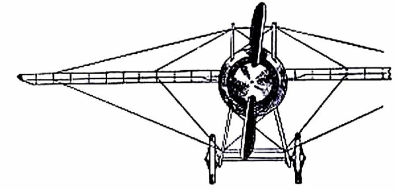
 (809 visites) showing the “stream-line” effect which is gained by tapering the body, also the simplification o...") Racing Deperdussin Monoplane (front view)
Racing Deperdussin Monoplane (front view)
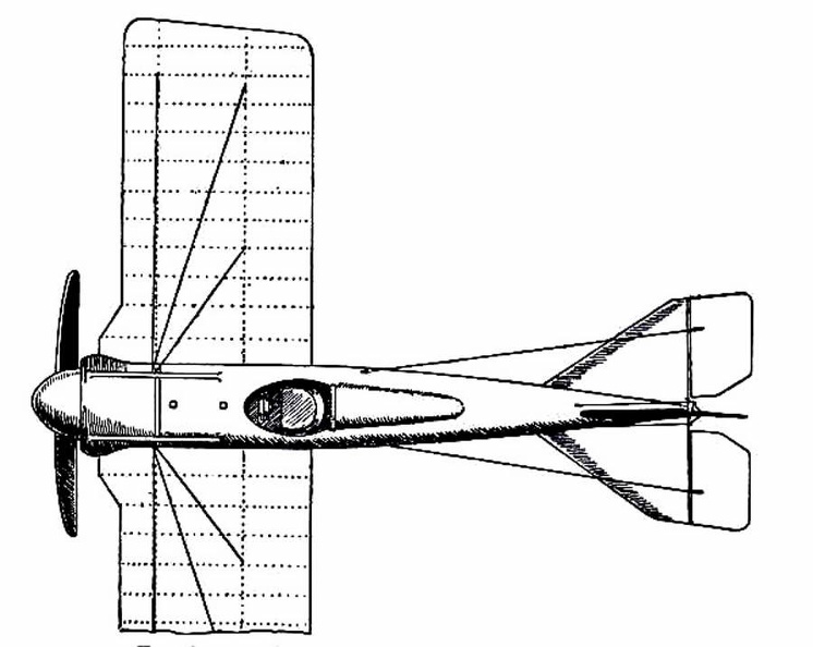
showing the “stream-line” effect which is gained by tapering the body, also the simplification of the landing chassis, and the use of a minimum of wires. photo id=7984] (909 visites)") Racing Deperdussin Monoplane (top view)
Racing Deperdussin Monoplane (top view) An Old-fashioned Train of Cars") An Old-fashioned Train of Cars
An Old-fashioned Train of Cars
An Old-fashioned Train of Cars During the Crimean War, Boydell’s traction machine was used to haul open trucks on the road and ac...") The 'Hercules' Traction Engine, as used during the Crimean War
The 'Hercules' Traction Engine, as used during the Crimean War
During the Crimean War, Boydell’s traction machine was used to haul open trucks on the road and across country. Its engine, the “Hercules,” was fitted with a curious arrangement, which, by means of rails attached in six sections to the wheels, enabled it to lay down and take up its own track as it went along.") A 'Fischer' Combination Omnibus
A 'Fischer' Combination Omnibus But a means of adapting a mono-rail to every condition had some time before been thought out. In 188...") Plan of a Behr Mono-Railway Car
Plan of a Behr Mono-Railway Car
But a means of adapting a mono-rail to every condition had some time before been thought out. In 1883-4 Charles Lartigue, the eminent French engineer, developing the principle conceived by the great Telford, constructed some small lines in Tunis and Algeria for carrying esparto grass. The cars were drawn by animals in a special form of mono-rail, the model upon which Mr. F. B. Behr, ASS. INST. C.E.—who modestly disclaims all originality in the matter—has worked for years, greatly improving in practical details the original design, and constructing for the first time mono-rail trains that have been successful in the carriage of both goods and passengers by steam and electricity. Electrical Power House (the largest in the Old World), Lot’s Road, Chelsea, to supply the Metropol...") Electrical Power House
Electrical Power House
Electrical Power House (the largest in the Old World), Lot’s Road, Chelsea, to supply the Metropolitan District and other Railways with Current") A Krupp motor gun-carrying lorry
A Krupp motor gun-carrying lorry") A ‘Schneider’ armoured car with quick-firing gun
A ‘Schneider’ armoured car with quick-firing gun") A ‘Charron’ armoured car with machine gun
A ‘Charron’ armoured car with machine gun") An Italian design for a motor battery of quick-firing guns
An Italian design for a motor battery of quick-firing guns") A type of extemporised motor ambulance favoured by the French and Belgians
A type of extemporised motor ambulance favoured by the French and Belgians") Travelling Post, 1825-35
Travelling Post, 1825-35") Royal Mail Coach
Royal Mail Coach The coaches that travelled between London and distant towns were similar in construction to the hack...") The Machine, 1640-1700
The Machine, 1640-1700
The coaches that travelled between London and distant towns were similar in construction to the hackney coach, which plied for hire in the streets, but were built on a larger scale. They carried eight passengers inside, and behind, over the axle, was a great basket for baggage and outside passengers, who made themselves as comfortable as they might in the straw supplied. The “insides” were protected from rain and cold by leather curtains; neither passengers nor baggage were carried on the roof; and the coachman sat on a bar fixed between the two standard posts from which the body was hung in front, his feet being supported by a footboard on the perch. Mr. Thrupp states that in 1662 there were only six stage coaches in existence; which assertion does not agree with that of Chamberlayne, quoted on a previous page; the seventeenth century writer tells us that in his time—1649—stage coaches ran “from London to the principle towns in the country.” It seems, however, certain that the year 1662 saw a great increase in the number of “short stages”—that is to say, coaches running between London and towns twenty, thirty, forty miles distant. Bourn’s reference to the “narrow-wheel waggon” touches a matter which formed the subject of ho...") Mr. Daniel Bourn’s Roller Wheel Waggon -1763
Mr. Daniel Bourn’s Roller Wheel Waggon -1763
Bourn’s reference to the “narrow-wheel waggon” touches a matter which formed the subject of hot debate for generations. It was urged that the narrow wheels of waggons were largely the means of cutting up the roads, and no doubt these did contribute to the general condition of rut and ridge that characterised them. This view was adopted by Parliament, and to encourage the use of wide wheels a system of turnpike tolls was adopted which treated the wide tire far more leniently than the narrow; anything under 9 inches in width being considered narrow. Bourn was a warm advocate for wide wheels, and the book from which the above passage is taken describes an improved waggon invented by himself; the drawing is[80] from the inventor’s work. The wheels of this vehicle resemble small garden rollers; they are 2 feet high and 16 inches wide. Each is attached independently to the body of the waggon and the fore wheels being placed side by side in the centre, while the hind wheels are set wide apart, the waggon is practically designed to fulfil the functions of a road-roller. It does not appear that Bourn’s invention obtained any general acceptance, which is perhaps not very surprising. Queen Elizabeth travelled in a coach, either the one built by Walter Rippon or that brought by Boone...") Queen Elizabeth’s Travelling Coach
Queen Elizabeth’s Travelling Coach
Queen Elizabeth travelled in a coach, either the one built by Walter Rippon or that brought by Boonen (who, by the way, was appointed her coachman), on some of her royal progresses through the kingdom. When she visited Warwick in 1572, at the request of the High Bailiff she “caused every part and side of the coach to be opened that all her subjects present might behold her, which most gladly they desired.” The vehicle which could thus be opened on “every part and side” is depicted incidentally in a work executed by Hoefnagel in 1582, which Markland believed to be probably the first engraved representation of an English coach. As will be seen from the reproduction here given, the body carried a roof or canopy on pillars, and the intervening spaces could be closed by means of curtains. (653 visites)") London Hackney Cab (Boulnois’ Patent)
London Hackney Cab (Boulnois’ Patent)") King George IV. in His Pony Phaeton
King George IV. in His Pony Phaeton, 1750 (618 visites)") Travelling Posting Carriage (2), 1750
Travelling Posting Carriage (2), 1750, 1750 (665 visites)") Travelling Posting Carriage (1), 1750
Travelling Posting Carriage (1), 1750 From Engraving, A.D. 1750.") Going to Bury Fair
Going to Bury Fair
From Engraving, A.D. 1750. Carriage used about 1300-1350 in Flanders.
Carriages were in use on the continent long before they ...") Flight of Princess Ermengarde
Flight of Princess Ermengarde
Carriage used about 1300-1350 in Flanders. Carriages were in use on the continent long before they were employed in England. In 1294, Philip the Fair of France issued an edict whose aim was the suppression of luxury; under this ordinance the wives of citizens were forbidden to use carriages, and the prohibition appears to have been rigorously enforced. They were used in Flanders during the first half of the fourteenth century; an ancient Flemish chronicle in the British Museum (Royal MSS. 16,[9] F. III.) contains a picture of the flight of Ermengarde, wife of Salvard, Lord of Rouissillon. Showing near-side “Boot.”
Coaches with \"Boots\"
From Coach and Sedan, we obtain a quaint bu...") Coach of Queen Elizabeth’s Ladies
Coach of Queen Elizabeth’s Ladies
Showing near-side “Boot.” Coaches with "Boots" From Coach and Sedan, we obtain a quaint but fairly graphic description of the coach of this period:— “The coach was a thick, burly, square-set fellow in a doublet of black leather, brasse button’d down the breast, back, sleeves and wings, with monstrous wide boots, fringed at the top with a net fringe, and a round breech (after the old fashion) gilded, and on his back an atchievement of sundry coats [of arms], in their proper colours.” The “boots” were projections at the sides of the body between the front and back wheels, as shown in the drawing of the coach occupied by Queen Elizabeth’s ladies; and there is much evidence to support the opinion that these boots were not covered. Horse litters, carried between two horses, one in front and one behind, were used in early times by ...") Horse Litter
Horse Litter
Horse litters, carried between two horses, one in front and one behind, were used in early times by ladies of `rank`, by sick persons, and also on occasion to carry the dead. Similar vehicles of a lighter description, carried by men, were also in use. William of Malmesbury states that the body of William Rufus was brought from the spot where he was killed in the New Forest in a horse-litter (a.d. 1100). When King John fell ill at Swineshead Abbey, in 1216, he was carried in a horse-litter to Newark, where he died. For a man who was in good health to travel in such a conveyance was considered unbecoming and effeminate. In recording the death, in 1254, of Earl Ferrers, from injuries received in an accident to his conveyance, Matthew Paris deems it necessary to explain that the Earl suffered from gout, which compelled him to use a litter when moving from place to place. The accident was caused by the carelessness of the driver of the horses, who upset the conveyance while crossing a bridge. The illustration is copied from a drawing which occurs in a manuscript in the British Museum (Harl. 5256). Supposed to have been in use in England about
A.D.. 1100-1200.
Strutt states that the chariot ...") Hammock Waggon
Hammock Waggon
Supposed to have been in use in England about A.D.. 1100-1200. Strutt states that the chariot of the Anglo-Saxons was used by distinguished persons for travel. If the illustrations from which he describes them give a fair idea of their proportions and general construction, they must have been singularly uncomfortable conveyances. The drawing is taken from an illuminated manuscript of the Book of Genesis in the Cotton Library (Claud. B. iv.), which Strutt refers to the ninth century, but which a later authority considers a production of the earlier part of the eleventh. The original drawing shows a figure in the hammock waggon, which figure represents Joseph on his way to meet Jacob on the latter’s arrival in Egypt; this figure has been erased in order to give a clear view of the conveyance, which no doubt correctly represents a travelling carriage of the artist’s own time, viz., a.d. 1100-1200. Excessive number of Coaches in London.
The preamble of a patent granted Sir Saunders Duncombe in ...") Hackney Coaches in London, 1637
Hackney Coaches in London, 1637
Excessive number of Coaches in London. The preamble of a patent granted Sir Saunders Duncombe in 1634 to let Sedan chairs refers to the fact that the streets of London and Westminster “are of late time so much encumbered and pestered with the unnecessary multitude of coaches therein used”; and in 1635 Charles I. issued a proclamation on the subject. This document states that the “general and promiscuous use” of hackney coaches in great numbers causes “disturbance” to the King and Queen personally, to the nobility and others of place and degree; “pesters” the streets, breaks up the pavements and cause increase in the prices of forage. For which reasons the use of hackney coaches in London and Westminster and the suburbs is forbidden altogether, unless the passenger is making a journey of at least three miles. Within the city limits only private coaches were allowed to ply, and the owner of a coach was required to keep four good horses or geldings for the king’s service.") Locomotive of To-day
Locomotive of To-day A \"No. 2 flying boat,\" just built by Mr. Curtiss, and successfully tested on Lake Keuka, Hammondspor...") Diagram of the Curtiss Flying Boat no. 2
Diagram of the Curtiss Flying Boat no. 2
A "No. 2 flying boat," just built by Mr. Curtiss, and successfully tested on Lake Keuka, Hammondsport, in July, 1912, is the "last word" in aviation so far. An illustration in this book, made from photographs taken in mid-July, 1912, shows fully the bullet-shape of the "flying fish." It is a real boat, built with a fish-shaped body containing two comfortable seats for the pilot and passenger or observer, either of whom can operate the machine by a system of dual control, making it also available for teaching the art of flying. All the controls are fastened to the rear of the boat's hull, which makes them very rigid and strong, while the boat itself, made in stream-line form, offers the least possible resistance to the air, even less than that offered by the landing gear upon a standard land machine. Above the boat are mounted the wings and aeroplane surface. In the centre of this standard biplane construction is situated the eighty horse-power motor with its propeller in the rear, thus returning to the original practice, as in the standard Curtiss machines, of having a single propeller attached direct to the motor, thus doing away with all chains and transmission gearing which might give trouble, and differing from the earlier model flying boat built in San Diego, California, last winter (1911-12), which was equipped with "tractor" propellors propellers in front driven by chains. The new flying boat is twenty-six feet long and three feet wide. The planes are five and a half feet deep and thirty feet wide. It runs on the water at a speed of fifty miles an hour, and is driven by an eighty horse-power Curtiss motor. At a greater speed than this it cannot be kept on the water, but rises in the air and flies at from fifty to sixty miles per hour. Following the success of the \"White Wing\" we started in to build another machine, embodying all that...") Scientific American Trophy
Scientific American Trophy
Following the success of the "White Wing" we started in to build another machine, embodying all that we had learned from our experience with the two previous ones. Following our custom of giving each machine a name to distinguish it from the preceding one, we called this third aeroplane the "June Bug." The name was aptly chosen, for it was a success from the very beginning. Indeed, it flew so well that we soon decided it was good enough to win the trophy which had been offered by The Scientific American for the first public flight of one kilometer, or five-eights of a mile, straightaway. This trophy, by the way, was the first to be offered in this country for an aeroplane flight, and the conditions specified that it should become the property of the person winning it three years in succession. The "June Bug" was given a thorough try-out before we made arrangements to fly for the trophy, and we were confident it would fulfill the requirements. 1. Cylinder; 2. Engine Bed; 3. Fuel Tank: 4. Oil Pan; 5. Radiator; 6. Propeller; 7. Crank Case; 8. C...") Diagram of Curtiss motor, side and front views
Diagram of Curtiss motor, side and front views
1. Cylinder; 2. Engine Bed; 3. Fuel Tank: 4. Oil Pan; 5. Radiator; 6. Propeller; 7. Crank Case; 8. Carbureter; 9. Gasoline Pipe; 10. Air Intake; 11. Auxiliary Air-pipe; 12. Drain Cock; 13. Water Cooling System; 14. Gas Intake Pipe; 15. Rocker Arm; 16. Spring on Intake Valve; 17. Spring on Exhaust Valve; 18. Exhaust Port; 19. Rocker Arm Post; 20. Push Rod. 1. Motor; 2. Radiator; 3. Fuel Tank; 4. Upper Main Plane; 5. Lower Main Plane; 6. Aileron; 7. Vertic...") Diagram of Curtiss Aeroplane, side view
Diagram of Curtiss Aeroplane, side view
1. Motor; 2. Radiator; 3. Fuel Tank; 4. Upper Main Plane; 5. Lower Main Plane; 6. Aileron; 7. Vertical Rudder; 8. Tail Surface; 9. Horizontal Rudder, or Rear Elevator; 10. Front Elevator; 11. Vertical Fin; 12. Steering Wheel; 13. Propeller; 14. Foot Throttle Lever; 15. Hand Throttle Lever; 16. Foot Brake. Gearless, 75 H.P. Gearless Transmission Co., Rochester, N. Y.
PRICE: $3,750
BODY: Side entr...") Gearless, 75 H.P
Gearless, 75 H.P
Gearless, 75 H.P. Gearless Transmission Co., Rochester, N. Y. PRICE: $3,750 BODY: Side entrance tonneau SEATS: 7 persons WEIGHT: 3,000 pounds WHEEL-BASE: 128 inches TREAD: 56 inches TIRES, FRONT: 36 × 4 inches TIRES, REAR: 36 × 4½ inches STEERING: Worm and nut BRAKES: On transmission and 2 on each rear hub SPRINGS: Semi-elliptical FRAME: Pressed steel BORE: 413/16 in.; STROKE: 5⅝ in. CYLINDERS: 6 vertical in front VALVE ARRANGEMENT: Inlet and exhaust in side ports MOTOR SUSPENSION: From sub-frame COOLING: Water IGNITION: Jump spark, 2 sets of plugs CURRENT SUPPLY: Storage battery and magneto CARBURETER: Float-feed LUBRICATION: Pump driven by gears MOTOR-CONTROL: Spark and throttle CLUTCH: Expanding ring CHANGE GEAR: Gearless 1907 model, direct drive SPEEDS: 2 forward and reverse CHANGE-GEAR CONTROL: Foot pedal for forward speeds; side lever for back up DRIVE: Shaft Hercules, Model 101. James Macnaughtan Co., Buffalo, N. Y.
PRICE: $2,000
BODY: Closed deliv...") Hercules, Model 101
Hercules, Model 101
Hercules, Model 101. James Macnaughtan Co., Buffalo, N. Y. PRICE: $2,000 BODY: Closed delivery wagon CAPACITY: 1,000 pounds WEIGHT: 2,700 pounds TIRES, FRONT: 34 × 2 inches TIRES, REAR: 36 × 2 inches STEERING: Horizontal side lever BRAKES: Internal expanding hub SPRINGS: Front, half platform; rear, full elliptical MOTORS: Single equipment MOTOR SUSPENSION: From body MOTOR-CONTROL: Westinghouse CHANGE SPEEDS: 4 forward and reverse DRIVE: Double chain Frontenac, Model C, 40 H.P. Abendroth & Root Mfg. Co., Newburgh, N. Y.
PRICE: $3,500
BODY: ...") Frontenac, Model C, 40 H.P
Frontenac, Model C, 40 H.P
Frontenac, Model C, 40 H.P. Abendroth & Root Mfg. Co., Newburgh, N. Y. PRICE: $3,500 BODY: Side entrance tonneau SEATS: 5 to 7 persons WEIGHT: 2,800 pounds WHEEL-BASE: 123 inches TREAD: 56 inches TIRES, FRONT: 34 × 4 inches TIRES, REAR: 34 × 4½ inches STEERING: Bevel gear connecting to worm and nut BRAKES: Internal and external on rear wheels BORE: 4¾ in.; STROKE: 5 in. SPRINGS: Semi-elliptical FRAME: Pressed steel CYLINDERS: 4, vertical in pairs VALVE ARRANGEMENT: On same side MOTOR SUSPENSION: From sub-frame COOLING: Water, fin tube radiator IGNITION: Jump spark CURRENT SUPPLY: Storage battery and magneto CARBURETER: Automatic LUBRICATION: Splash MOTOR-CONTROL: Spark and throttle CHANGE GEAR: Sliding type SPEEDS: 3 forward and reverse CHANGE-GEAR CONTROL: Selective system DRIVE: Shaft Gearless, 50 H.P. Gearless Transmission Co., Rochester, N. Y.
PRICE: $3,000
BODY: Side entr...") Gearless, 50 H.P
Gearless, 50 H.P
Gearless, 50 H.P. Gearless Transmission Co., Rochester, N. Y. PRICE: $3,000 BODY: Side entrance tonneau SEATS: 5 persons WEIGHT: 2,600 pounds WHEEL-BASE: 124 inches TREAD: 56 inches TIRES, FRONT: 36 × 4 inches TIRES, REAR: 36 × 4 inches STEERING: Worm and nut BRAKES: On transmission and two on each rear hub SPRINGS: Semi-elliptical FRAME: Pressed steel BORE: 4⅝ in.; STROKE: 5 in. CYLINDERS: 4, vertical in front; two cycle MOTOR SUSPENSION: From sub-frame COOLING: Air jackets. Blower; copper fins cast on cylinders IGNITION: Jump spark CURRENT SUPPLY: Storage battery and dry cells CARBURETER: Float-feed LUBRICATION: Mechanical force feed oiler MOTOR-CONTROL: Spark and throttle CLUTCH: Expanding ring CHANGE GEAR: Gearless 1907 model, direct drive SPEEDS: 2 forward and reverse CHANGE-GEAR CONTROL: Foot pedal for forward speeds; ride lever for reverse DRIVE: Shaft Gearless, 60 H.P. Gearless Transmission Co., Rochester, N. Y.
PRICE: $3,250
BODY: Side entr...") Gearless, 60 H.P
Gearless, 60 H.P
Gearless, 60 H.P. Gearless Transmission Co., Rochester, N. Y. PRICE: $3,250 BODY: Side entrance tonneau SEATS: 5 persons WEIGHT: 2,800 pounds WHEEL-BASE: 124 inches TREAD: 56 inches TIRES, FRONT: 36 × 4 inches TIRES, REAR: 36 × 4 inches STEERING: Worm and nut BRAKES: On transmission and rear hubs SPRINGS: Semi-elliptical FRAME: Pressed steel BORE: 5 in.; STROKE: 5 in. CYLINDERS: 4 vertical in front, 2 cycle MOTOR SUSPENSION: From sub-frame COOLING: Water IGNITION: Double jump spark CURRENT SUPPLY: Magneto and battery CARBURETER: Float-feed LUBRICATION: Mechanical force feed MOTOR-CONTROL: Spark and throttle CLUTCH: Expanding ring CHANGE GEAR: Gearless direct drive SPEEDS: 2 forward and reverse CHANGE-GEAR CONTROL: Side lever and foot pedal DRIVE: Shaft Covert Commercial Car, 12 H.P. Covert Motor Vehicle Co., Lockport, N. Y.
PRICE: $1,000
BODY...") Covert Commercial Car, 12 H.P
Covert Commercial Car, 12 H.P
Covert Commercial Car, 12 H.P. Covert Motor Vehicle Co., Lockport, N. Y. PRICE: $1,000 BODY: Express (screen sides) CAPACITY: 1,000 pounds WEIGHT: 1,500 pounds WHEEL-BASE: 84 inches TREAD: 56 inches TIRES, FRONT: 32 × 2 inches TIRES, REAR: 32 × 2 inches SPRINGS: Full elliptic CYLINDERS: Double opposed MOTOR SUSPENSION: From side members of frame, under seat COOLING: Water; cellular radiator IGNITION: Jump spark CURRENT SUPPLY: Batteries CHANGE GEAR: Sliding type CHANGE-GEAR CONTROL: Side lever DRIVE: Shaft and bevel gears Frontenac Runabout, Model D, 40–45 H.P. Abendroth and Root M'f'g. Co., Newburgh, N. Y.
PRI...") Frontenac Runabout, Model D, 40–45 H.P
Frontenac Runabout, Model D, 40–45 H.P
Frontenac Runabout, Model D, 40–45 H.P. Abendroth and Root M'f'g. Co., Newburgh, N. Y. PRICE: $3,500 BODY: Runabout SEATS: 3 persons WEIGHT: 2,500 pounds WHEEL-BASE: 123 inches TREAD: 56 inches TIRES, FRONT: 36 × 3½ in. TIRES, REAR: 36 × 4½ in. STEERING: Bevel gear and shaft connecting to worm and nut BRAKES: External and internal on rear wheels SPRINGS: Semi-elliptical FRAME: Pressed steel BORE: 4¾ in.; STROKE: 5 in. CYLINDERS: 4 vertical, in pairs VALVE ARRANGEMENT: On one side MOTOR SUSPENSION: Sub-frame COOLING: Water; fin tube radiator IGNITION: Jump spark (double) CURRENT SUPPLY: Magneto and battery CARBURETER: Automatic float-feed LUBRICATION: Splash MOTOR-CONTROL: Spark and throttle CHANGE GEAR: Sliding type SPEEDS: 3 forward and reverse CHANGE-GEAR CONTROL: Selective system DRIVE: Shaft Chicago Coal or Gravel Truck. Chicago Commercial Auto Mfg. Co., Chicago, Ill.
BODY: Tilting
...") Chicago Coal or Gravel Truck
Chicago Coal or Gravel Truck
Chicago Coal or Gravel Truck. Chicago Commercial Auto Mfg. Co., Chicago, Ill. BODY: Tilting CAPACITY: 5 tons WHEEL-BASE: 126 inches TREAD: 64 inches TIRES, FRONT: 36 inches, solid rubber TIRES, REAR: 36 inches, solid rubber BRAKES: On transmission shaft and rear hubs SPRINGS: Platform type FRAME: Steel BORE: 6 inches STROKE: 6 inches CYLINDERS: 4, cast separate VALVE ARRANGEMENT: in cylinder heads on same side MOTOR SUSPENSION: Under seat COOLING: Water IGNITION: Jump spark CURRENT SUPPLY: Batteries or magneto CARBURETER: Float-feed type LUBRICATION: Mechanical force feed MOTOR-CONTROL: Spark and throttle CLUTCH: Cast steel bands with graphite inserts CHANGE GEAR: Sliding type SPEEDS: 3 forward and reverse CHANGE-GEAR CONTROL: Side lever DRIVE: Side chains Chicago Combination Pass. & Bagg. Car. Chicago Commercial Auto Mfg. Co., Chicago, Ill.
BODY:...") Chicago Combination Pass. & Bagg. Car
Chicago Combination Pass. & Bagg. Car
Chicago Combination Pass. & Bagg. Car. Chicago Commercial Auto Mfg. Co., Chicago, Ill. BODY: Passenger and baggage car SEATS: 16 persons WHEEL-BASE: 126 inches TREAD: 64 inches TIRES, FRONT: 36 inches, solid rubber TIRES, REAR: 36 inches, solid rubber BRAKES: On transmission shaft and rear wheels SPRINGS: Platform type FRAME: Steel BORE: 6 inches STROKE: 6 inches CYLINDERS: 4 vertical, separate VALVE ARRANGEMENT: In cylinder heads, on same side MOTOR SUSPENSION: Under seat COOLING: Water IGNITION: Jump spark CURRENT SUPPLY: Batteries or magneto CARBURETER: Float-feed LUBRICATION: Mechanical force feed MOTOR-CONTROL: Spark and throttle CLUTCH: Cast steel band with graphite inserts CHANGE GEAR: Sliding type SPEEDS: 3 forward and reverse CHANGE-GEAR CONTROL: Side lever DRIVE: Side chains Chicago Truck with Winch. Chicago Commercial Auto Mfg. Co., Chicago, Ill.
BODY: Platform tru...") Chicago Truck with Winch
Chicago Truck with Winch
Chicago Truck with Winch. Chicago Commercial Auto Mfg. Co., Chicago, Ill. BODY: Platform truck with winch CAPACITY: 5 tons WHEEL-BASE: 126 inches TREAD: 64 inches TIRES, FRONT: 36 inches, solid rubber TIRES, REAR: 36 inches, solid rubber STEERING: Vertical column BRAKES: On transmission and rear hubs SPRINGS: Platform type FRAME: Steel BORE: 6 inches STROKE: 6 inches CYLINDERS: 4, cast separate VALVE ARRANGEMENT: In cylinder heads, operated from one side MOTOR SUSPENSION: Under driver's seat COOLING: Water IGNITION: Jump spark CURRENT SUPPLY: Batteries or magneto CARBURETER: Float-feed type LUBRICATION: Forced feed oiler MOTOR-CONTROL: Spark and throttle CLUTCH: Cast steel bands with graphite inserts CHANGE GEAR: Sliding type SPEEDS: 3 forward and reverse CHANGE-GEAR CONTROL: Side lever DRIVE: Double side chain