


") Yale 1910
Yale 1910 When the Wrights had built an engine, there was still the question how they should make it drive the...") Wright Motor and Propellers
Wright Motor and Propellers
When the Wrights had built an engine, there was still the question how they should make it drive their aeroplane. They inclined naturally to the idea of an aerial propeller. Two courses lay open to them; they could fit one propeller running at high speed and coupled directly to the motor, or they could use two propellers, revolving at slower speed and geared in some way to the engine. They decided upon the latter course, placing two propellers behind the main planes of their machine and driving them from the engine by means of light chains, these running in guiding tubes. This system of propulsion is shown. A. Motor; B. Gear-wheels upon motor crank-shaft; C.C. Tubes carrying driving chains; D.D. Sprocket-wheels over which chains pass; E.E. Propellers. A. Biplane; B. Rail; C. Rope passing from the aeroplane round the pulley-wheel (D.) and thence to th...") Wright Launching Rail
Wright Launching Rail
A. Biplane; B. Rail; C. Rope passing from the aeroplane round the pulley-wheel (D.) and thence to the derrick (E.); (F.) Falling weight. Details of propulsion and control being arranged, there remained the question of how the machine should be launched into the air. In their gliding tests, it will be remembered, the Wrights employed assistants, who held the machine by the wing-tips and ran forward with it. But the weight of the power-driven machine, and its greater size, prevented such a plan as this. They decided, therefore, to launch it from a rail, and to aid its forward speed, at the moment of taking the air, by a derrick and a falling weight. Whistling bouy
Less picturesque than lighthouses and lightships, and with far less of human inter...") Whistling bouy
Whistling bouy
Whistling bouy Less picturesque than lighthouses and lightships, and with far less of human interest about them, are the buoys of various sorts of which the Lighthouse Board has more than one thousand in place, and under constant supervision. Yet, among the sailor's safeguards, they `rank` near the head. They point out for him the tortuous pathway into different harbors; with clanging bell or dismal whistle, they warn him away from menacing shallows and sunken wrecks. The resources of science and inventive genius have been drawn upon to devise ways for making them more effective. At night they shine with electric lights fed from a submarine cable, or with steady gas drawn from a reservoir that needs refilling only three or four times a year. If sound is to be trusted rather than light, recourse is had to a bell-buoy which tolls mournfully as the waves toss it about above the danger spot, or to a whistling buoy which toots unceasingly a locomotive whistle, with air compressed by the Page 355action of the waves. The whistling buoy is the giant of his family, for the necessity for providing a heavy charge of compressed air compels the attachment to the buoy of a tube thirty-two feet or more deep, which reaches straight down into the water. The sea rising and falling in this, as the buoy tosses on the waves, acts as a sort of piston, driving out the air through the whistle, as the water rises, admitting more air as it falls. Whale sending boat flying
While the right whale usually takes the steel sullenly, and dies like a...") Whale sending boat flying
Whale sending boat flying
Whale sending boat flying While the right whale usually takes the steel sullenly, and dies like an overgrown seal, the cachalot fights fiercely, now diving with such a rush that he has been known to break his jaw by the fury with which he strikes the bottom at the depth of 200 fathoms; now raising his enormous bulk in air, to fall with an all-obliterating crash upon the boat which holds his tormentors, or sending boat and men flying into the air with a furious blow of his gristly flukes, or turning on his back and crunching his assailants between his cavernous jaws.
Patent Iron Suspension Railroad Bridge.
The undersigned would inform the officers of Railroads ...") Wendell Bollmans Patent Bridge
Wendell Bollmans Patent Bridge
Patent Iron Suspension Railroad Bridge. The undersigned would inform the officers of Railroads and others, that he is prepared to furnish Drawings and Estimates for Bridges, Roofs, etc., on the plan of Bollman’s Patent. The performance of these bridges, some of which have been in use for six years, has given entire satisfaction. Their simplicity of construction renders repairs easy and cheap, and by a peculiar connection of the Main and Panel Rods at the bottom of the Posts, all danger from the effects of expansion, which has heretofore been the chief objection to Iron Bridges, is entirely removed. J. H. TEGMEYER, Baltimore, Md. The Waterfront of New York") Waterfront
Waterfront
The Waterfront of New York We must remember that travelling was no such simple and easy matter then as it is now. As the plante...") Washington's Coach
Washington's Coach
We must remember that travelling was no such simple and easy matter then as it is now. As the planters in Virginia usually lived on the banks of one of the many rivers, the simplest method of travel was by boat, up or down stream. There were cross-country roads, but these at best were rough, and sometimes full of roots and stumps. Often they were nothing more than forest paths. In trying to follow such roads the traveler at times lost his way and occasionally had to spend a night in the woods. But with even such makeshifts for roads, the planter had his lumbering old coach to which, on state occasions, he harnessed six horses and drove in great style.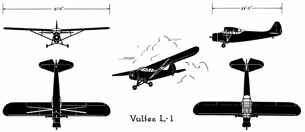 Vultee L-1
Vultee L-1 Front Side Perspective Bottom Top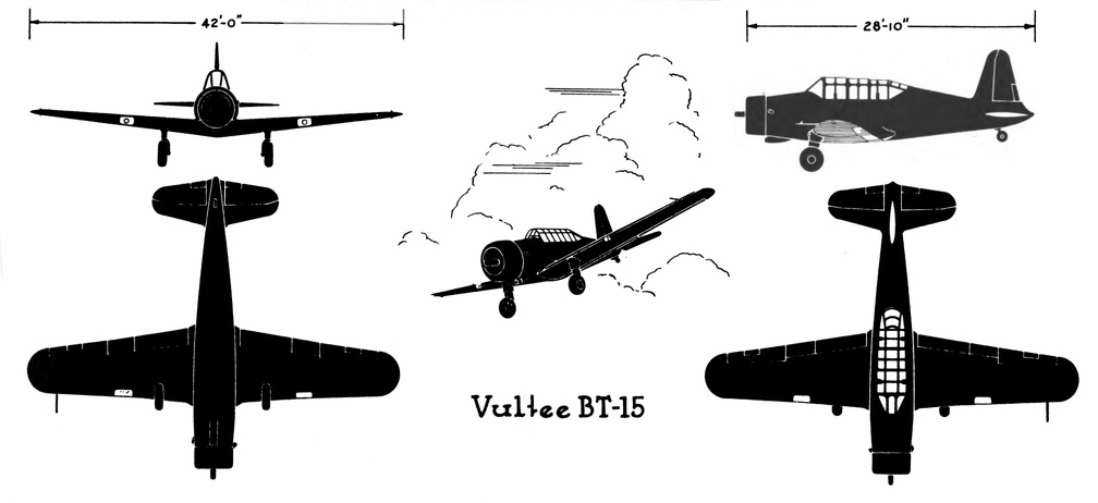 Vultee BT-15
Vultee BT-15 Front Side Perspective Bottom Top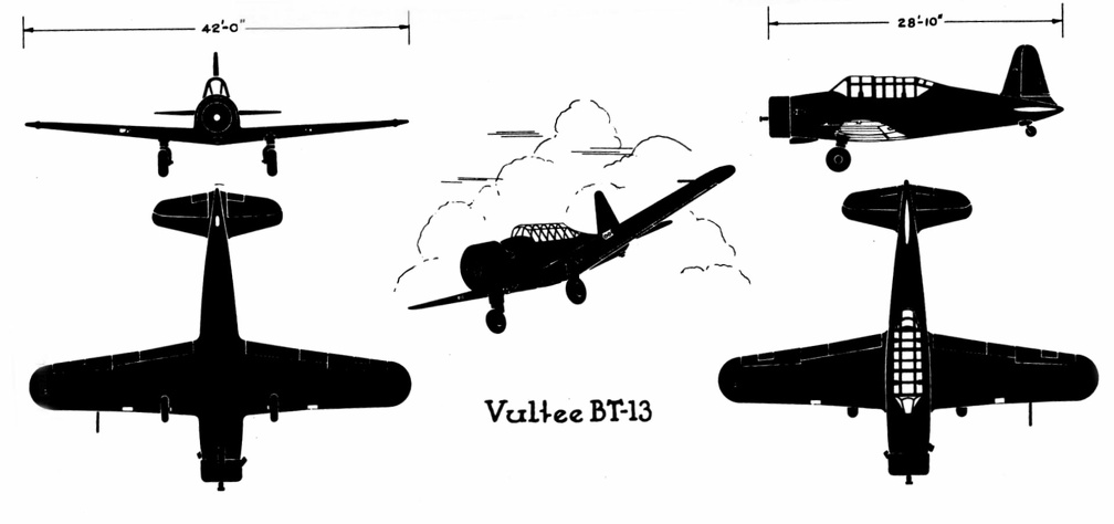 Vultee BT-13
Vultee BT-13 Front Side Perspective Bottom Top Vultee A-31
Front Side
...") Vultee A-31
Vultee A-31
Vultee A-31 Front Side Perspective Bottom Top In the launching of gliders, some French experimenters showed ingenuity. The brothers Voisin, for in...") Voisin Glider towed by a motor-car
Voisin Glider towed by a motor-car
In the launching of gliders, some French experimenters showed ingenuity. The brothers Voisin, for instance, who played a prominent part in the early tests in France, adopted the plan illustrated. The gilder was towed by a motor-car across an open stretch of ground; then, when its speed was sufficient for the planes to lift, it rose and flew behind the car like a kite. A form of glider, mounted upon hollow wooden floats—anticipating the sea-plane of to-day—and tow...") Voisin Glider on the river Seine
Voisin Glider on the river Seine
A form of glider, mounted upon hollow wooden floats—anticipating the sea-plane of to-day—and towed upon the river Seine by a motor-boat. This gilder also, when its speed became sufficient, rose into the air. In the construction of the machine, a biplane, one notes resemblances to the method of the Wrights; and yet generally the craft is dissimilar. The article upon the Velocipede in the \" American Encyclopedia,\" commences by giving the well-known ...") Velocipedes
Velocipedes
The article upon the Velocipede in the " American Encyclopedia," commences by giving the well-known derivation of the word from the Latin velox, swift, and pes, a foot, and defines it as a carriage, by means of which the rider propels himself along the ground, and states that it was invented at Manheim. We present a bicycle for ladies, lately invented and patented by Messrs. Pickering & Davis of New Yo...") Velocipede for Ladies
Velocipede for Ladies
We present a bicycle for ladies, lately invented and patented by Messrs. Pickering & Davis of New York City. It will be seen that the reach or frame, instead of forming a nearly straight line from the front swivel to the hind axle, follows the curve of the front wheel until it reaches a line nearly as low as the hind axle when it runs horizontally to that point of the hind wheel. The two wheels being separated three or four inches, allow of an upright rod being secured to the reach; around this is a spiral spring, on which a comfortable, cane-seated, willow-backed chair is placed. This machine, with a moderate-sized wheel (of thirty to thirty-three inches), will allow being driven with a great deal of comfort and all the advantages of the two-wheel veloce. In mounting, a lady has to step over the reach, at a point only twelve inches from the floor, the height of an ordinary step in a flight of stairs. If you have to take a side road on the right, keep your arm stretched out in horizontal direction o...") Turn Signal
Turn Signal
If you have to take a side road on the right, keep your arm stretched out in horizontal direction outside the car. [Translated online from the Dutch ] There needs to be an equipment of spare machines also; and a number of travelling workshops with ski...") Travelling workshop for the repair of military aeroplanes
Travelling workshop for the repair of military aeroplanes
There needs to be an equipment of spare machines also; and a number of travelling workshops with skilled engineers, which can be rushed from place to place for the repair of damaged craft. A sketch of one of these workshops on wheels, which are vital to the organisation, is seen in the figure Air raid siren in Paris") Tooting the sirens of warning
Tooting the sirens of warning
Air raid siren in Paris British plane flying over the trenches in the great war") They swoop down over the trenches
They swoop down over the trenches
British plane flying over the trenches in the great war Apart from governing the ascending or descending movement, there was the question of preventing a ma...") The Wright Wing-warp
The Wright Wing-warp
Apart from governing the ascending or descending movement, there was the question of preventing a machine from slipping sideways; and this the Wrights solved ingeniously. They saw, of course, that when their glider lurched to one side or the other, they would need some power to tilt it back again. So they devised a system by which the plane-ends of their machine—being made flexible—might be warped, or caused to shift up and down. This action the operator controlled, as he lay across the lower plane, by a movement of cords, and its operation is shown in Figure. The effect upon the machine may be described thus: should a wind-gust tilt down one plane-end, the “warp” upon that side of the machine was drawn down also, and the effect of this—seeing that it caused the plane to assume a steeper angle to the air and exercise a greater lift—was to raise the plane-ends that had been driven down by the gust. By a system of connecting the control cords, this balancing influence was made to act with double force; when one wing warped down, the other moved up; and, in this way, while the side of the machine tilted down was made to rise, the other plane-ends, which had been lifted, were made to descend. A dual righting influence was thus obtained. This system, which imitates the flexing movements made by a bird, was an important device; the Wrights patented it—combining the movement with an action of the rudder—and brought cases at law to enforce their rights. The Wright Brothers Aero Engine") The Wright Brothers Aero Engine
The Wright Brothers Aero Engine
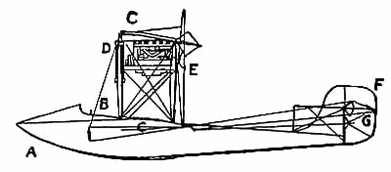
The Wright Brothers Aero Engine A.A.—Main-planes; B. Double front elevator; C. Rudder (two narrow vertical planes); D. Motor; E. P...") The Wright Biplane
The Wright Biplane
A.A.—Main-planes; B. Double front elevator; C. Rudder (two narrow vertical planes); D. Motor; E. Propellers; F. Pilot’s lever; G. Skids upon which machine landed. It is now possible to describe, as a completed craft, the Wright power-driven plane; The picture shows its appearance; and in looking at it one is struck by the fact that, save for one or two modifications, and the fitting of motor and propellers, the machine is practically a glider, such as the Wrights used for soaring tests. Of the changes to be observed, the most interesting concern the elevator and rear-rudder. The former, it will be seen, has a double plane; it is, in fact, a smaller biplane on the principle of the main-planes. Needing to increase the surface of the elevator, the brothers fixed one plane above another so as to make the construction stronger and occupy less space. The rear-rudder, acting like that of a ship. The Whaleback
Another form of lake vessel of which great things were expected, but which disappoi...") The Whaleback
The Whaleback
The Whaleback Another form of lake vessel of which great things were expected, but which disappointed its promotors, is the "whaleback," commonly called by the sailors "pigs." These are cigar-shaped craft, built of steel, their decks, from the bridge aft to the engine-house, rounded like the back of a whale, and carried only a few feet above the water. In a sea, the greater part of the deck is all awash, and a trip from the bridge to the engine-house means not only repeated duckings, but a fair chance of being swept overboard. The Voisin Biplane - top view") The Voisin Biplane - top view
The Voisin Biplane - top view
The Voisin Biplane - top view At the beginning of 1909 there were two types of successful aeroplane—the Wright and the Voisin. B...") The Voisin Biplane
The Voisin Biplane
At the beginning of 1909 there were two types of successful aeroplane—the Wright and the Voisin. Bleriot had flown with his monoplane and flown well; but he was still in the process of evolving a practical machine, and several other inventors were in a similar stage. It was the Wright and the Voisin which had proved their worth; and the Wright, as has been said, was the better of the two. Of the Voisin, as flown in 1909, a reproduction is given in the figure. It was a heavier aeroplane than the Wrights’, owing largely to the weight of its alighting gear (250 lbs.) and of its big balancing tail (more than 100 lbs.); hence the necessity for using a 50-h.p. motor, which drove a two-bladed metal propeller at the rate of 1200 revolutions a minute. The Voisin brothers, and other French makers, did not approve of the two-propeller system of the Wrights: they preferred one screw, revolving at high speed. But there was no doubt—at any rate in this stage of aviation—that the Wright method was more efficient than that of the Frenchmen. It was calculated, indeed, that the Wright biplane, when actually in the air, could be driven at an expenditure of only 15 h.p.; whereas the Voisin, even with its 50-h.p. motor running at full speed, had only just enough power to fly. A. Elevating plane B. Pilot’s seat C.C. Main-planes D. Engine and propeller E. Landing chassis F. Balancing tail G. Rudder. Already, anticipating war in the air, a fighting aeroplane has been evolved; and a machine of this t...") The Vickers
The Vickers
Already, anticipating war in the air, a fighting aeroplane has been evolved; and a machine of this type is shown in Figure. The body, in which pilot and gunner sit, is armoured lightly with plates which will resist the penetration of a bullet. Such armouring was found necessary after the use of aeroplanes in Tripoli and the Balkans. When flying unavoidably low in these campaigns, and when fired at from the ground, the wooden bodies of machines were pierced by shot, and in several instances their occupants wounded. A fighting aeroplane A. Machine-gun projecting from opening in bow B. Gunner’s position C. Pilot’s seat D.D. Side windows for observation E. Engine and propeller. The Treachourous Kayak
Mastering all the literature of the Arctic, he (Charles Hall) determined t...") The Treachourous Kayak
The Treachourous Kayak
The Treachourous Kayak Mastering all the literature of the Arctic, he (Charles Hall) determined to undertake himself the arduous work of the explorer. Taking passage on a whaler, he spent several years among the Esquimaux, living in their crowded and fetid igloos, devouring the blubber and uncooked fish that form their staple articles of diet, wearing their garb of furs, learning to navigate the treacherous kayak in tossing seas, to direct the yelping, quarreling team of dogs over fields of ice as rugged as the edge of some monstrous saw, studying the geography so far as known of the Arctic regions, perfecting himself in all the arts by which man has contested the supremacy of that land with the ice-king. The Snow. an obsolete type") The Snow. an obsolete type
The Snow. an obsolete type
The Snow. an obsolete type A. Enclosed body
B. Driver’s position
C. Steering wheel
D. Foot-controlled throttle lever for e...") The single-seated 'air-car'—a suggested type
The single-seated 'air-car'—a suggested type
A. Enclosed body B. Driver’s position C. Steering wheel D. Foot-controlled throttle lever for engine E.E. The two sustaining-planes F. The motor G. Propeller H. Rudder I. Elevating-plane J. Landing gear. First probably for mails, and after this for passenger-carrying, will aeroplanes of the future be employed; and they will find a scientific use, too, in exploring remote corners of the earth, and in passing above forests which are now impenetrable. Small, fast machines, much cheaper than those of to-day, will be bought also for private use—many of them, as suggested by the figure, having room for only one man within their hulls. Then there will be flying clubs; and to these, after their day’s work, will come a city’s toilers. Through the cheapening of craft, as time goes on, practically all members of the community will experience the joys of flight. Thus, say on a summer’s evening, the doors of the sheds will be pushed aside, and the machines wheeled out and overhauled; then, one by one, these small, fast-moving craft will rise into the air and dart here and there—circling, manœuvring, dipping, and diving.") The Shallop
The Shallop The difficulty with air-cooling—although it had obvious advantages over water-cooling—was to bri...") The seven-cylinder 50-h.p. Gnome motor.
The seven-cylinder 50-h.p. Gnome motor.
The difficulty with air-cooling—although it had obvious advantages over water-cooling—was to bring enough air to play upon the surfaces of the cylinders; and it was here that the Gnome won so complete a success. In other engines the cylinders were stationary, and their pistons, moving up and down in the cylinders, turned a crank-shaft to the end of which the propeller was fixed. Therefore the only air the cylinders obtained was what rushed upon them through the speed of the machine in flight. But in the Gnome, instead of the cylinders remaining stationary and the crank-shaft revolving, the cylinders themselves spun round, and the crank-shaft did not move. An illustration of this motor with one end of the crank-chamber removed, so that the piston-rods can be seen, is given in the figure. It will be noted that there are seven cylinders, set in the form of a star, and that the seven piston-rods projecting from them come together upon a single crank-pin, which is attached to the stationary crank-shaft and turns round it. The propeller, instead of being fitted to the crank-shaft, as was the case with other motors, was bolted to a plate upon the engine itself, so that when this turned around its crank-shaft, it carried the propeller with it. The seaplane shoots off the catapult") The seaplane shoots off the catapult
The seaplane shoots off the catapult
The seaplane shoots off the catapult An experimenter who braved this apathy and won his way until he became a constructor of aircraft, wa...") The Roe Triplane
The Roe Triplane
An experimenter who braved this apathy and won his way until he became a constructor of aircraft, was Mr. A. V. Roe. For some time he was an advocate of the triplane form of machine—a craft, that is to say, with three main-planes fitted one above another. The machine with which he obtained flights, although they were very brief, is seen in the figure. Subsequently, however, Mr. Roe adopted the biplane form. His distinction in the pioneer days was that he managed to make his triplane lift into the air and fly a short distance, with the aid of a motor-cycle engine developing no more than 9 h.p. A.A.A. Three main-planes B. Motor C. Four-bladed propeller D.D.D. Triplane tail E. Rudder F. Landing gear. In 1830 all this had disappeared, and we find in Mr. Nasmyth's sketch a regular fire-box, such as is...") The Rocket 1830
The Rocket 1830
In 1830 all this had disappeared, and we find in Mr. Nasmyth's sketch a regular fire-box, such as is used to this moment. In one word, the Rocket of 1829 is different from the Rocket of 1830 in almost every conceivable respect; and we are driven perforce to the conclusion that the Rocket of 1829 never worked at all on the Liverpool and Manchester Railway; the engine of 1830 was an entirely new engine. The \"Jersey\" prison-ship was not an uncommon lot for the bold privateersman, who, when once consigne...") The Prison Ship 'Jersey'
The Prison Ship 'Jersey'
The "Jersey" prison-ship was not an uncommon lot for the bold privateersman, who, when once consigned to it, found that the reward of a sea-rover was not always wealth and pleasure. The "Jersey," which had been originally a 74-gun ship, then cut down to a hulk and moored at the Wallabout, at that time a lonely and deserted place on the Long Island shore, now about the center of the Brooklyn river front. The engines drove two canvas-covered wooden screws, each 18 feet in length, and the general appearan...") The Maxim Machine
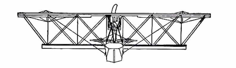
The Maxim Machine
The engines drove two canvas-covered wooden screws, each 18 feet in length, and the general appearance of the machine is indicated by the picture. In these trials, although it was always captive, the aeroplane demonstrated much that its inventor had set himself to prove. In Sir Hiram Maxim’s own words, it showed that it had “a lifting effect of more than a ton, in addition to the weight of three men and 600 lbs. of water.” He adds: “My machine demonstrated one very important fact, and that was that very large aeroplanes had a fair degree of lifting power for their area.” The ketch was a two-master, sometimes rigged with lanteen sails, but more often with the foremast sq...") The Ketch
The Ketch
The ketch was a two-master, sometimes rigged with lanteen sails, but more often with the foremast square-rigged, like a ship's foremast, and the mainmast like the mizzen of a modern bark, with a square topsail surmounting a fore-and-aft mainsail. The foremast was set very much aft—often nearly amidships. A. Pilot’s seat and controlling wheel
B. Passenger’s seat
C. Movable flap to facilitate enteri...") The hull of a Flying-Boat
The hull of a Flying-Boat
A. Pilot’s seat and controlling wheel B. Passenger’s seat C. Movable flap to facilitate entering the hull D. Handle, like that of a car, for starting the engine E. The engine F. Fuel tanks G. The propeller.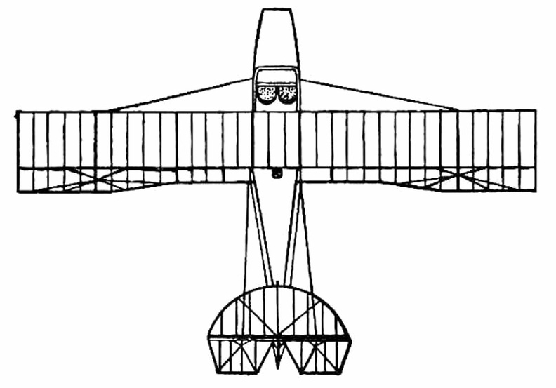
 Piracy was an everyday occurence for the sailors.") The Gun was disharged
The Gun was disharged
Piracy was an everyday occurence for the sailors. Some of the earliest three-deckers, or, as we may almost call them, five-deckers, were built at this...") The Great Harry
The Great Harry
Some of the earliest three-deckers, or, as we may almost call them, five-deckers, were built at this dockyard; and of these the most famous was the Great Harry, so named after the king, which was launched here in 1514. For the period, the ship was a large one, being of a thousand tons burden; though we should not think much of her size now, when we have ironclads of over eleven thousand tons. There are models of her in the Greenwich Naval Museum, which is not far from Woolwich; and a curious lofty wooden castle she is, rising far up above the water-line, and offering a fair target, if the cannon of those days had any accuracy.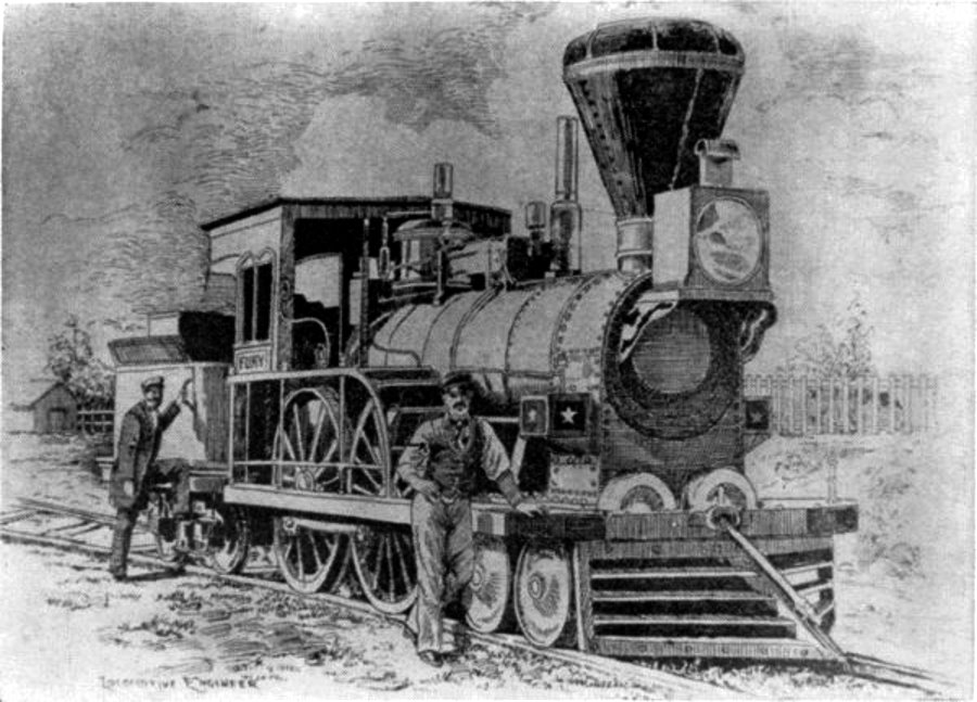 The Fury
The “Fury,” built for the Boston and Worcester Railroad in 1849 by Wilmarth. It was known as a “Shanghai” because of its great height. It was called the 'Locomotion.' George Stephenson stood ready to drive it as soon as the trucks, whi...") The first Railway Journey in England
The first Railway Journey in England
It was called the 'Locomotion.' George Stephenson stood ready to drive it as soon as the trucks, which a stationary engine was lowering down the slope by means of a wire rope, had been attached to it. In the first of these trucks came the Directors of the Railway Company and their friends, followed by twenty-one trucks (all open to the sky, like ordinary goods-trucks), loaded with various passengers, and finally six more waggons of coal. Such was the first train. A man on horseback, carrying a flag, having taken up his position in front of the 'Locomotion' to head the procession, the starting word was given, and with a hiss of steam, half drowned in the shouting of the crowd, the first railway journey ever made in England was begun. showing the span of main-planes, elevator, and tail, also the positions of landing gear and pilot’...") The Farman Biplane - top view
The Farman Biplane - top view
showing the span of main-planes, elevator, and tail, also the positions of landing gear and pilot’s seat.
In July, at Rheims, there was to be the great flying meeting; and Farman had made up his mind to...") The Farman Biplane
The Farman Biplane
In July, at Rheims, there was to be the great flying meeting; and Farman had made up his mind to wait for this. Aided by the experience he had gained with the Voisin machine, he had designed a craft which should be generally more efficient and faster in flight, and more quickly responsive to its controls. The biplane he produced, marking as it did a step forward in construction, is a machine that needs description. The general appearance of the craft is indicated by Fig. 46, while an illustration of this type of machine in flight will be found on Plate VII. A feature of the Voisin that Farman discarded was the vertical panel fitted between the main-planes to give sideway stability. An objection to these planes was that they added to the weight of the machine and checked its speed, tending also to drive it from its course should there be a side wind. But in taking away such fixed balancing-planes, Farman had to substitute another device; and what he did was to work upon the same theory as the Wrights had done, and obtain a similar result in a different way. They, it will be remembered, had warped the rear portions of their main-planes. Farman kept his planes rigid, but fitted to their rear extremities four narrow, hinged planes, or flaps, which could be moved up and down and were called ailerons. Their effect was the same as with the Wright wing-warp. When a gust tilted the machine, the pilot drew down the ailerons upon the side that was inclined downward; whereupon the air-pressure, acting upon the drawn-down surfaces, restored the machine to an even keel. A. Elevating-plane; B.B. Main-planes; C. Pilot’s seat; D. Motor and propeller; E. Petrol tank; F.F. Hinged balancing-planes, or ailerons; G.G. Tail-planes; H.H. Twin vertical rudders; I. Landing wheels and skid The Dreadnaught") The Dreadnaught
The Dreadnaught
The Dreadnaught The depth bomb destroys a U-Boat") The depth bomb destroys a U-Boat
The depth bomb destroys a U-Boat
The depth bomb destroys a U-Boat The Dandy-horse of 1818, the two wheels on which the rider sat astride, tipping the ground with his ...") The Dandy-horse
The Dandy-horse
The Dandy-horse of 1818, the two wheels on which the rider sat astride, tipping the ground with his feet in order to propel the machine, was laughed out of existence. The Curtiss Biplane making a turn") The Curtiss Biplane making a turn
The Curtiss Biplane making a turn
The Curtiss Biplane making a turn The Curtiss Biplane in flight") The Curtiss Biplane in flight
The Curtiss Biplane in flight
The Curtiss Biplane in flight showing the chassis and the position between the planes of the two ailerons (A.A.).") The Curtiss Biplane front view
The Curtiss Biplane front view
showing the chassis and the position between the planes of the two ailerons (A.A.). Of famous aeroplanes at Rheims, five types stood out by themselves—the Farman, the Voisin, the Wri...") The Curtiss Biplane
The Curtiss Biplane
Of famous aeroplanes at Rheims, five types stood out by themselves—the Farman, the Voisin, the Wright, the Bleriot, and the Antoinette, all of which have been described. But there was one other, which few people had heard of before it appeared here. This was the Curtiss biplane, built by an American named Glenn H. Curtiss, and engined with a motor which also bore his name. Curtiss had experimented with many power-driven machines—motor-cycles, motor-cars, airships, and aeroplanes—and had won a prize in America with a small, light biplane, and it was a craft of this type—as seen in the figure —that he brought with him to Rheims, his idea being to compete for the speed prize. The machine had a front elevator and tail-planes, according to the practice in biplane construction; but an innovation was the setting of the ailerons midway between the main-planes—a position that will be noted in the sketch; another novelty was the way these ailerons operated. At the pilot’s back, as he sat in his driving seat, was an upright rod with two shoulder-pieces—by means of which, should he shift his body, he could swing the rod from side to side. Wires ran from the rod to the ailerons; and if the pilot leaned over, say, to the right, he drew down the ailerons on the left side of the machine. The merit of such a control was that it was instinctive; that is to say, should the biplane tip down on one side, it was natural for the pilot to lean away from the plane-ends that were sinking; and he operated the ailerons automatically, as he did this, and so brought the machine level again. A. Elevating-planes B. Pilot’s seat and control-wheel C.C. Main-planes D. Ailerons E. Motor and propeller F. Tail-plane and rudder. showing the large size of the elevators, the position of the pilot, and the placing of the propeller...") The Cody Biplane from above
The Cody Biplane from above
showing the large size of the elevators, the position of the pilot, and the placing of the propellers. Another ardent worker in England, and one destined to become famous, was Mr. S. F. Cody. After devel...") The Cody Biplane
The Cody Biplane
Another ardent worker in England, and one destined to become famous, was Mr. S. F. Cody. After developing a system of man-lifting kites which the British War Office acquired, he joined the military aircraft factory that had been established at Farnborough. Here, after tests with dirigible balloons, he began the construction of experimental biplanes—all machines of large size. Early in 1909 he made brief flights—the longest being one of about 250 yards. Then, after alterations to his machine, he managed in July to fly a distance of 4 miles. This he increased afterwards to 8 miles; and then on 1st September flew for 1 hour 3 minutes, rising to a height of 300 feet. Cody’s biplane was a very large machine, having 1000 square feet of lifting surface—twice that of the Farman or Voisin. Driving it was an 80-h.p. engine, which operated two propellers on the system used by the Wrights. With its pilot on board the machine weighed 2170 lbs. A. Elevating-planes and vertical-plane B. Pilot’s control lever C.C. Main-planes D. Motor E. Propellers F. Rudder G. Landing gear H. Rear skid. A.A. Ballast bags filled with sand
B. Instruments (such as a statoscope, which shows at any moment ...") The car of a modern Balloon
The car of a modern Balloon
A.A. Ballast bags filled with sand B. Instruments (such as a statoscope, which shows at any moment whether the balloon is rising or falling; and an altitude meter) C. Ring by which car is attached to balloon. For the fisheries a multitude of smaller types were constructed—such as the lugger, the shallop, t...") The Bug-Eye
The Bug-Eye
For the fisheries a multitude of smaller types were constructed—such as the lugger, the shallop, the sharpie, the bug-eye, the smack. The Bleriot Monoplane - top view showing its bird-like shape and the position of the pilot.") The Bleriot Monoplane - top view
The Bleriot Monoplane - top view
The Bleriot Monoplane - top view showing its bird-like shape and the position of the pilot. A. Propeller
B. Motor
C. Sustaining-plane
D. Pilot’s seat
E. Landing chassis
F. Combined tail...") The Bleriot Monoplane
The Bleriot Monoplane
A. Propeller B. Motor C. Sustaining-plane D. Pilot’s seat E. Landing chassis F. Combined tail and elevating-planes G. Rudder. Of the various kinds of velocipedes, four, three, two, and one wheeled, the bicycle seems to be cons...") The Bicycle
The Bicycle
Of the various kinds of velocipedes, four, three, two, and one wheeled, the bicycle seems to be considered the most artistic, is altogether the most in favor, and steadily maintains its ground against all rivals. Whether it will be the model velocipede of the future remains to be seen. The various experiments now being tried will, no doubt, eventually result in a nearly perfect machine, but it will require a season's experience fully to develop the ingenuity of our American artisans. Many have expressed doubts as to the real utility of the velocipede, and the permanency of its use. They seem to think it a frivolous invention only calculated to serve purposes of amusement, and soon to be superseded by some other ephemeral claimant for popularity. Most of these have based their opinions upon the disuse into which rude machines have fallen in former times. But the difference in the construction of the modern velocipede from the primitive one has entirely changed the character of the vehicle. It is no longer a draft vehicle, but a locomotive, and as much superior to the original bar on wheels, as the improved steam locomotive is to the old-time stage-coach. It was on June 5, 1783 that Stephen and Joseph Montgolfier, two French brothers, sent up the first b...") The ascension of Montgolfier’s balloon
The ascension of Montgolfier’s balloon
It was on June 5, 1783 that Stephen and Joseph Montgolfier, two French brothers, sent up the first balloon. You can just imagine the amazement it caused when it arose from the ground.