


« 2020
2022 »
Janvier
Février
Mars
Avril
Mai
Juin
Juillet
Août
Septembre
Octobre
Novembre
Décembre
Tout

") Royal Mail Coach
Royal Mail Coach") A 'Fischer' Combination Omnibus
A 'Fischer' Combination Omnibus") A type of extemporised motor ambulance favoured by the French and Belgians
A type of extemporised motor ambulance favoured by the French and Belgians") Banked turn on a biplane
Banked turn on a biplane, 1750 (618 visites)") Travelling Posting Carriage (2), 1750
Travelling Posting Carriage (2), 1750") Travelling Post, 1825-35
Travelling Post, 1825-35") King George IV. in His Pony Phaeton
King George IV. in His Pony Phaeton") Construction of a Monoplane wing
Construction of a Monoplane wing (653 visites)") London Hackney Cab (Boulnois’ Patent)
London Hackney Cab (Boulnois’ Patent), 1750 (665 visites)") Travelling Posting Carriage (1), 1750
Travelling Posting Carriage (1), 1750 Langley built his plane without much difficulty, but could not find anyone to make an engine large e...") The Aerodrome
The Aerodrome
Langley built his plane without much difficulty, but could not find anyone to make an engine large enough for it. Finally, Charles Manley, an expert engineer, asked for permission to build the engine. Manley’s engine was a five-cylinder, radial gasoline engine that developed 51 horsepower and was far ahead of its time. It was years before American radial engines were used successfully in airplanes. Professor Langley called his machine the Aerodrome, and by October, 1903, the plane was ready for its test flight, with Manley to guide it. The Aerodrome was to be launched from a catapulting platform built on the roof of a houseboat. The houseboat was anchored on the Potomac River near Washington. As it left the platform the machine crashed into the river, and the trial was a dismal failure. The newspapers and the public ridiculed Langley, but he and Manley, who was unhurt in the crash, repaired the machine for another trial. This test took place on December 8, 1903, and again the Aerodrome crashed into the river. Manley once more escaped injury, but Langley and the government were abused by the public for wasting money. Langley was out of money himself, the government could not furnish funds for further trials, so the experiments were ended. The professor, discouraged and brokenhearted, gave up. During the Crimean War, Boydell’s traction machine was used to haul open trucks on the road and ac...") The 'Hercules' Traction Engine, as used during the Crimean War
The 'Hercules' Traction Engine, as used during the Crimean War
During the Crimean War, Boydell’s traction machine was used to haul open trucks on the road and across country. Its engine, the “Hercules,” was fitted with a curious arrangement, which, by means of rails attached in six sections to the wheels, enabled it to lay down and take up its own track as it went along.") A Krupp motor gun-carrying lorry
A Krupp motor gun-carrying lorry (800 visites) In the development of speed, some remarkable craft are built. Each year there is an international ai...") Racing Deperdussin Monoplane (side view)
Racing Deperdussin Monoplane (side view)
In the development of speed, some remarkable craft are built. Each year there is an international air race for the possession of the Gordon-Bennett trophy, and to win this designers build special craft. In tiny monoplanes, engines of high power are installed; and the sustaining wings are so reduced, to give a maximum speed, that the machines appear more like projectiles than flying craft. A purely racing-type monoplane is seen in figure.. It represents a Deperdussin, which, with an engine of 160 horse-power, reached a speed of 130 miles an hour. How small this machine was, in relation to its engine-power, will be realised from the fact that the sustaining surface of its wings amounted to only 104 square feet—far less lifting area, in fact, than Lilienthal used in his gliders. Wires and struts are reduced to a minimum; the body is tapered and smoothed. Such a machine, although it carries speed to an extreme, and is in reality a “freak,” teaches useful lessons. But though it provides data for the construction of high-speed scouts, a monoplane of this type would be useless for cross-country flying; and for the reason that it cannot be manœuvred, prior to an ascent, upon anything save the smoothest of ground. Its wings being so small, to ensure a maximum of speed, the machine will not rise until it has run forward a long distance across the ground; and during this run it attains a speed of nearly 90 miles an hour. At such a pace, unless the ground below its wheels was level, it would leap, swerve, and probably overturn. When alighting from a flight, also, again owing to the smallness of its wings, the craft has to plane down so fast that its pilot could not land safely unless he had below him a surface that was absolutely smooth. A. Propeller B. Shield to lessen wind resistance C. Sloping shield which encloses engine (also to minimise wind-pressure). Air passes between the shields B and C to cool the motor. D. Pilot’s seat E. Padded projection against which, when at high speed, the pilot rests his head F. Sustaining-plane Very slightly cambered G. Rudder H. Elevating-plane I. Landing wheels.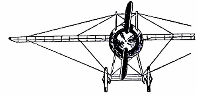
 (809 visites) showing the “stream-line” effect which is gained by tapering the body, also the simplification o...") Racing Deperdussin Monoplane (front view)
Racing Deperdussin Monoplane (front view)
showing the “stream-line” effect which is gained by tapering the body, also the simplification of the landing chassis, and the use of a minimum of wires. photo id=7984] An experiment was made by Patrick Miller, a banker in Edinburgh, aided by Mr. Taylor, tutor in his f...") Miller’s twin boat on Loch Dalswinton, 1788
Miller’s twin boat on Loch Dalswinton, 1788
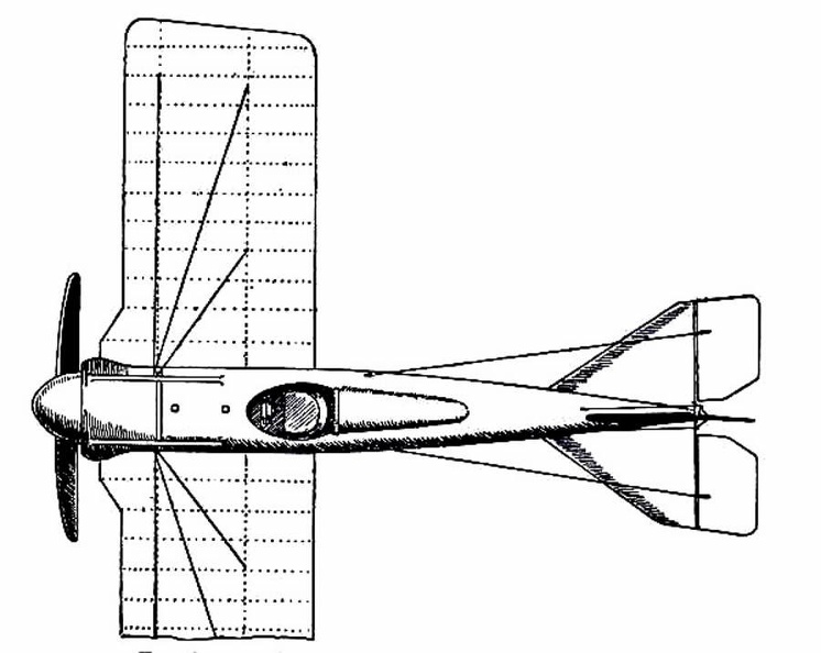
An experiment was made by Patrick Miller, a banker in Edinburgh, aided by Mr. Taylor, tutor in his family, and Alexander Symington, a practical engineer. Mr. Miller had a boat built and fitted with a small steam-engine, for his amusement, on Dalswinton Loch, Dumfriesshire. It was a twin-boat, the engine being placed on one side, the boiler on the other, and the paddle-wheel in the centre. It was launched in October, 1788, and attained a speed of five miles an hour. The engine, of one horse-power, is still to be seen in the Andersonian Museum, in Glasgow. Encouraged by his experiment, Mr. Miller bought one of the boats used on the Forth and Clyde Canal, and had a steam-engine constructed for it by the Carron Ironworks Company, under Symington’s superintendence. On December 26th, 1789, this steamboat towed a heavy load on the canal, at a speed of seven miles an hour; but, strange to say, the experiment was dropped as soon as it was tried. (909 visites)") Racing Deperdussin Monoplane (top view)
Racing Deperdussin Monoplane (top view)") A ‘Schneider’ armoured car with quick-firing gun
A ‘Schneider’ armoured car with quick-firing gun Fifty years later witnessed the full development of Mr. Bell’s ideal in the Columba, then as now t...") “Columba,” famous Clyde river steamer, 1875
“Columba,” famous Clyde river steamer, 1875
Fifty years later witnessed the full development of Mr. Bell’s ideal in the Columba, then as now the largest river steamer ever seen on the Clyde, and the swiftest. The Columba is built of steel, is 316 feet long and 50 feet wide. She has two oscillating engines of 220 horse-power, and attains a speed of twenty-two miles an hour. Her route is from Glasgow to Ardrishaig and back, daily in summer, when she carries from 2,000 to 3,000 persons through some of the finest scenery in Scotland. She is provided with steam machinery for steering and warping her into the piers, and with other modern appliances that make her as handy as a steam yacht. She resembles a little floating town, with shops and post-office where you can procure money orders and despatch telegrams And what is the Columba after all but an enlarged and perfected reproduction of Bell’s Comet!") An Italian design for a motor battery of quick-firing guns
An Italian design for a motor battery of quick-firing guns after testing more than 200 wing designs and plane surfaces in their wind tunnel, the Wright Brother...") The Four forces of flight
The Four forces of flight
after testing more than 200 wing designs and plane surfaces in their wind tunnel, the Wright Brothers found out how to figure correctly the amount of curve, or camber, that was essential to weight-carrying wings. They discovered, too, that before man could be flown through the air, he must have his wings attached firmly to a body or platform which was firm and controllable. The Wrights in their earliest experiments had realized that to be practical their machine must be built not only to fly in a straight line, but also in order that it could be steered to the right or to the left. One day, Orville was twisting a cardboard box in his hand when Wilbur noticed it. Immediately he saw the solution to the problem of steering their airplane. The result was a design which changed the lift of either end of the wing by warping its surface. If one end of the wing was warped to give it more lift, the machine would lift on that side and fall off into a turn. Thus the problem of steering was solved by the Wrights") A ‘Charron’ armoured car with machine gun
A ‘Charron’ armoured car with machine gun The driver of a modern-type aeroplane, sitting snugly within its hull, has a wheel and instrument-bo...") The Control of a Biplane
The Control of a Biplane
The driver of a modern-type aeroplane, sitting snugly within its hull, has a wheel and instrument-board before him, as sketched. As he flies across country he has many things to think of. Holding the control-wheel in both hands, his feet resting upon the rudder-bar, his eyes rove constantly among the instruments [Pg 163]on the dashboard before him. He glances at the compass often, for it is by this that he steers; and when the air is clear, and the earth below plainly seen, he will every now and then glance over the side of the hull, so as to be on the look-out for a landmark that may tell him he is on his course. A. Pilot’s seat B. Hand-wheel (pushed forward or backward operates elevator; twisted sideways works ailerons) C. Foot-bar actuating rudder D. Compass E. Dial showing number of revolutions per minute that engine is making F. Gauge showing pressure in petrol tank G. Speed indicator H. Dial showing altitude I. Clock J. Switch for cutting off ignition. But a means of adapting a mono-rail to every condition had some time before been thought out. In 188...") Plan of a Behr Mono-Railway Car
Plan of a Behr Mono-Railway Car
But a means of adapting a mono-rail to every condition had some time before been thought out. In 1883-4 Charles Lartigue, the eminent French engineer, developing the principle conceived by the great Telford, constructed some small lines in Tunis and Algeria for carrying esparto grass. The cars were drawn by animals in a special form of mono-rail, the model upon which Mr. F. B. Behr, ASS. INST. C.E.—who modestly disclaims all originality in the matter—has worked for years, greatly improving in practical details the original design, and constructing for the first time mono-rail trains that have been successful in the carriage of both goods and passengers by steam and electricity. In 1801 the London newspapers contained the announcement that an experiment had taken place on the T...") Symington’s ‘Charlotte Dundas,’ 1802
Symington’s ‘Charlotte Dundas,’ 1802
In 1801 the London newspapers contained the announcement that an experiment had taken place on the Thames, on July 1st, for the purpose of propelling a laden barge, or other craft, against the tide, by means of a steam-engine of a very simple construction. “The moment the engine was set to work the barge was brought about, answering her helm quickly, and she made way against a strong current, at the rate of two and a half miles an hour.” In 1802 a new vessel was built expressly for steam navigation, on the Forth and Clyde Canal, under Symington’s supervision, the Charlotte Dundas, which was minutely inspected on the same day by Robert Fulton, of New York, and Henry Bell, of Glasgow, both of whom took sketches of the machinery to good purpose. This boat drew a load of seventy tons, at a speed of three and a half miles an hour, against a strong gale of wind. Under ordinary conditions she made six miles an hour, but her admitted success was cut short by the Canal Trust, who alleged that the wash of the steamer would destroy the embankment. 10-Passenger Limousine. Autocar Equipment Co., Buffalo, N. Y.
PRICE: $5,500
BODY: Limousine...") 10-Passenger Limousine
10-Passenger Limousine
10-Passenger Limousine. Autocar Equipment Co., Buffalo, N. Y. PRICE: $5,500 BODY: Limousine SEATS: 10 persons inside, 2 outside TREAD: 62½ inches TIRES, FRONT: 36 × 3½ in. TIRES, REAR: 36 × 4 in. STEERING: Irreversible with worm gear BRAKES: On counter shaft, and double-acting on rear hubs SPRINGS: Semi-elliptic FRAME: Oak and steel BORE: 411/16 in. STROKE: 5½ in. CYLINDERS: 4 vertical, separate VALVE ARRANGEMENT: On opposite sides COOLING: Water, cellular radiator IGNITION: Jump spark CURRENT SUPPLY: Batteries CARBURETER: Float-feed automatic LUBRICATION: Force feed MOTOR-CONTROL: Spark and throttle CLUTCH: Conical type CHANGE GEAR: Sliding type SPEEDS: 3 forward and reverse CHANGE-GEAR CONTROL: Side lever DRIVE: Double chain Nothing more was heard of the steamboat in Britain until 1812, when Henry Bell surprised the natives...") Bell’s ‘Comet,’ off Dumbarton on the Clyde, 1812
Bell’s ‘Comet,’ off Dumbarton on the Clyde, 1812
Nothing more was heard of the steamboat in Britain until 1812, when Henry Bell surprised the natives of Strathclyde by the following advertisement in the Greenock Advertiser: STEAM PASSAGE BOAT, “THE COMET,” Between Glasgow, Greenock and Helensburgh, for Passengers Only. The subscriber having, at much expense, fitted up a handsome vessel, to ply upon the River Clyde, between Glasgow and Greenock, to sail by the power of wind, air and steam, he intends that the vessel shall leave the Broomielaw on Tuesdays, Thursdays and Saturdays, about mid-day, or at such hour thereafter as may answer from the state of the tide; and to leave Greenock on Mondays, Wednesdays and Fridays, in the morning, to suit the tide. The elegance, comfort, safety and speed of this vessel requires only to be proved to meet the approbation of the public; and the proprietor is determined to do everything in his power to merit public encouragement. The terms are, for the present, fixed at 4s. for the best cabin, and 3s. for the second; but beyond these rates nothing is to be allowed to servants, or any other person employed about the vessel. The subscriber continues his establishment at Helensburgh Baths, the same as for years past, and a vessel will be in readiness to convey passengers to the Comet from Greenock to Helensburgh. Henry Bell. Helensburgh Baths, 5th August, 1812. Out in Dayton, Ohio, there were two small brothers, who dreamed, as countless other children before ...") Wright Brothers' Bicycle shop
Wright Brothers' Bicycle shop
Out in Dayton, Ohio, there were two small brothers, who dreamed, as countless other children before them had dreamed, of flying like birds through the air. Their dreams were heightened by a small toy given to them by their father, the pastor of a local church. This toy was to lead to an idea which had a profound effect on the world. You would probably call it a flying propeller. It consisted of a wooden propeller which slipped over a notched stick. By placing a finger against the propeller and rapidly pushing it up the notched stick, the propeller was made to whirl up off the end of the stick and fly into the air. The brothers, young as they were, never quite forgot this little toy as they continued to dream of flying like birds through the air. Though the brothers continued to dream of flying, they were not the kind of lads who spent all their time in dreaming. They made kites which flew a little better and a little higher than those made by the other boys in the neighborhood. They built a press to print their own little newspaper, and they dabbled in woodcuts. To carve out porch posts for their father’s home they built an eight-foot wood-turning lathe. Indeed, they were the sort of boys who caused the neighbors to say, “What will they think of next?” The brothers knew that if they ever wanted to see their dreams come true they must earn their own capital. In the early nineties America was in the midst of the bicycle craze. Everyone who could possibly afford to do so owned a bicycle of some sort and belonged to a cycle club. Being mechanically minded, the brothers did the logical thing. They set themselves up in a small bicycle shop in Dayton, next door to their home. The bicycle shop in Dayton prospered, for the brothers were careful and expert mechanics, and cyclists in need of repairs made their way to the Wright Brothers’ shop. The Wright Brothers were not only inspired mechanics (as many people still believe today) but seriou...") Wright Brotherrs wind tunnel
Wright Brotherrs wind tunnel
The Wright Brothers were not only inspired mechanics (as many people still believe today) but serious scientists, working along the soundest lines. In their keen desire to know what air pressure on wings really was, they cleared a corner of their bicycle shop and built a small wind tunnel with spare lumber and an old electric fan. They built small wing sections of various shapes and experimented with them in their wind tunnel. The electric fan was used to create the moving air around the wing section. By attaching the wing sections to a supporting frame and connecting the frame with a pointer and dial, they were able to keep a record of the effect of moving air on each experimental wing section. Through their wind tunnel research the Wright Brothers discovered the four forces that control all heavier-than-air flight: lift, thrust, weight, and drag. The Clermont made her first voyage from New York to Albany, August 7th, 1807.
Her speed was about ...") Fulton’s ‘Clermont’ on The Hudson, 1807
Fulton’s ‘Clermont’ on The Hudson, 1807
The Clermont made her first voyage from New York to Albany, August 7th, 1807. Her speed was about five miles an hour. During the winter of 1807-8 she was enlarged, her name being then changed to North River. She continued to ply successfully on the Hudson as a passenger boat for a number of years, her owners having acquired the exclusive right to navigate the waters of the State of New York by steam. Chicago Combination Pass. & Bagg. Car. Chicago Commercial Auto Mfg. Co., Chicago, Ill.
BODY:...") Chicago Combination Pass. & Bagg. Car
Chicago Combination Pass. & Bagg. Car
Chicago Combination Pass. & Bagg. Car. Chicago Commercial Auto Mfg. Co., Chicago, Ill. BODY: Passenger and baggage car SEATS: 16 persons WHEEL-BASE: 126 inches TREAD: 64 inches TIRES, FRONT: 36 inches, solid rubber TIRES, REAR: 36 inches, solid rubber BRAKES: On transmission shaft and rear wheels SPRINGS: Platform type FRAME: Steel BORE: 6 inches STROKE: 6 inches CYLINDERS: 4 vertical, separate VALVE ARRANGEMENT: In cylinder heads, on same side MOTOR SUSPENSION: Under seat COOLING: Water IGNITION: Jump spark CURRENT SUPPLY: Batteries or magneto CARBURETER: Float-feed LUBRICATION: Mechanical force feed MOTOR-CONTROL: Spark and throttle CLUTCH: Cast steel band with graphite inserts CHANGE GEAR: Sliding type SPEEDS: 3 forward and reverse CHANGE-GEAR CONTROL: Side lever DRIVE: Side chains 1. Cylinder; 2. Engine Bed; 3. Fuel Tank: 4. Oil Pan; 5. Radiator; 6. Propeller; 7. Crank Case; 8. C...") Diagram of Curtiss motor, side and front views
Diagram of Curtiss motor, side and front views
1. Cylinder; 2. Engine Bed; 3. Fuel Tank: 4. Oil Pan; 5. Radiator; 6. Propeller; 7. Crank Case; 8. Carbureter; 9. Gasoline Pipe; 10. Air Intake; 11. Auxiliary Air-pipe; 12. Drain Cock; 13. Water Cooling System; 14. Gas Intake Pipe; 15. Rocker Arm; 16. Spring on Intake Valve; 17. Spring on Exhaust Valve; 18. Exhaust Port; 19. Rocker Arm Post; 20. Push Rod. Hercules, Model 120. James Macnaughtan Co., Buffalo, N. Y.
PRICE: $1,750
BODY: Delivery wag...") Hercules, Model 120
Hercules, Model 120
Hercules, Model 120. James Macnaughtan Co., Buffalo, N. Y. PRICE: $1,750 BODY: Delivery wagon (closed) CAPACITY: 1,000 pounds WEIGHT: 2,300 pounds TIRES, FRONT: 34 × 2½ inches TIRES, REAR: 36 × 2½ inches STEERING: Side bar BRAKES: Band brakes on rear axle SPRINGS: Front, elliptic; rear, platform MOTORS: Double equipment MOTOR SUSPENSION: From body MOTOR-CONTROL: Westinghouse SPEEDS: 4 speeds ahead and reverse DRIVE: Double chain Historians have unearthed stories in cuneiform writing of man’s attempts to fly. Some of these ins...") The flight of Etana
The flight of Etana
Historians have unearthed stories in cuneiform writing of man’s attempts to fly. Some of these inscriptions date back more than five thousand years, to 3500 B.C. Perhaps the most famous of these stories is the ancient Babylonian tale of the shepherd boy, Etana, who rode on the back of an eagle. Chicago Coal or Gravel Truck. Chicago Commercial Auto Mfg. Co., Chicago, Ill.
BODY: Tilting
...") Chicago Coal or Gravel Truck
Chicago Coal or Gravel Truck
Chicago Coal or Gravel Truck. Chicago Commercial Auto Mfg. Co., Chicago, Ill. BODY: Tilting CAPACITY: 5 tons WHEEL-BASE: 126 inches TREAD: 64 inches TIRES, FRONT: 36 inches, solid rubber TIRES, REAR: 36 inches, solid rubber BRAKES: On transmission shaft and rear hubs SPRINGS: Platform type FRAME: Steel BORE: 6 inches STROKE: 6 inches CYLINDERS: 4, cast separate VALVE ARRANGEMENT: in cylinder heads on same side MOTOR SUSPENSION: Under seat COOLING: Water IGNITION: Jump spark CURRENT SUPPLY: Batteries or magneto CARBURETER: Float-feed type LUBRICATION: Mechanical force feed MOTOR-CONTROL: Spark and throttle CLUTCH: Cast steel bands with graphite inserts CHANGE GEAR: Sliding type SPEEDS: 3 forward and reverse CHANGE-GEAR CONTROL: Side lever DRIVE: Side chains Put together scientifically and from sections of wood specially tested, a remarkable strength may be...") Testing the girder-built body of an aircraft
Testing the girder-built body of an aircraft
Put together scientifically and from sections of wood specially tested, a remarkable strength may be obtained by such a method of building. The figure shows how a girder aircraft body, supported by trestles only at its ends, may support from its centre, without yielding, a tray containing a number of heavy weights Supposed to have been in use in England about
A.D.. 1100-1200.
Strutt states that the chariot ...") Hammock Waggon
Hammock Waggon
Supposed to have been in use in England about A.D.. 1100-1200. Strutt states that the chariot of the Anglo-Saxons was used by distinguished persons for travel. If the illustrations from which he describes them give a fair idea of their proportions and general construction, they must have been singularly uncomfortable conveyances. The drawing is taken from an illuminated manuscript of the Book of Genesis in the Cotton Library (Claud. B. iv.), which Strutt refers to the ninth century, but which a later authority considers a production of the earlier part of the eleventh. The original drawing shows a figure in the hammock waggon, which figure represents Joseph on his way to meet Jacob on the latter’s arrival in Egypt; this figure has been erased in order to give a clear view of the conveyance, which no doubt correctly represents a travelling carriage of the artist’s own time, viz., a.d. 1100-1200. Last of the Clipper Passenger Packets, 1854.
The clipper “packet ship” was a vast improvement...") 'Great Republic'
'Great Republic'
Last of the Clipper Passenger Packets, 1854. The clipper “packet ship” was a vast improvement on the ordinary sailing ship. It had just reached its highest point of development when the ocean steamship first made its appearance. It was to the upper strata of the travelling community, sixty years ago, the counterpart of the express steamer of to-day. The packet-ship was built for fast sailing, with very fine lines, was handsomely fitted up and furnished, was exceedingly well found in eatables and drinkables, and carried a great spread of canvas. To see one of these ships under full sail was a [Pg 27]sight to be remembered—a rare sight, inasmuch as all the conditions of wind and water necessary for the display of every stitch of canvas are seldom met with in the North Atlantic. They not unfrequently crossed in fourteen or fifteen days. In winter they might be three months on a single voyage, but their average would be from twenty-five to thirty days. Hercules, Model 113. James Macnaughtan Co., Buffalo, N. Y.
PRICE: $3,750
BODY: Platform tru...") Hercules, Model 113
Hercules, Model 113
Hercules, Model 113. James Macnaughtan Co., Buffalo, N. Y. PRICE: $3,750 BODY: Platform truck CAPACITY: 7,000 pounds WEIGHT: 7,500 pounds WHEEL-BASE: 118 inches TREAD: 70 inches TIRES, FRONT: 36 × 5 inches TIRES, REAR: 38 × 5 inches STEERING: Pinion and sector type BRAKES: Internal expanding hub SPRINGS: Semi-elliptic MOTORS: Double equipment MOTOR SUSPENSION: From body SPEED: 8 m.p.h. MOTOR-CONTROL: Westinghouse DISTANCE: 30 miles CHANGE SPEEDS: 4 forward and reverse DRIVE: Double chain Hercules, Model 102. James Macnaughtan Co., Buffalo, N. Y.
PRICE: $2,000
BODY: Delivery wag...") Hercules, Model 102
Hercules, Model 102
Hercules, Model 102. James Macnaughtan Co., Buffalo, N. Y. PRICE: $2,000 BODY: Delivery wagon (closed) CAPACITY: 800 pounds WEIGHT: 2,576 pounds TIRES, FRONT: 34 × 2 inches TIRES, REAR: 36 × 2 inches STEERING: Horizontal side lever BRAKES: Internal expanding hub SPRINGS: Front, half platform; rear, full elliptical MOTORS: Single equipment MOTOR SUSPENSION: From body MOTOR-CONTROL: Westinghouse SPEED: 12 m.p.h. CHANGE SPEEDS: 4 forward and reverse DISTANCE: 40 miles DRIVE: Double chain 1. Motor; 2. Radiator; 3. Fuel Tank; 4. Upper Main Plane; 5. Lower Main Plane; 6. Aileron; 7. Vertic...") Diagram of Curtiss Aeroplane, side view
Diagram of Curtiss Aeroplane, side view
1. Motor; 2. Radiator; 3. Fuel Tank; 4. Upper Main Plane; 5. Lower Main Plane; 6. Aileron; 7. Vertical Rudder; 8. Tail Surface; 9. Horizontal Rudder, or Rear Elevator; 10. Front Elevator; 11. Vertical Fin; 12. Steering Wheel; 13. Propeller; 14. Foot Throttle Lever; 15. Hand Throttle Lever; 16. Foot Brake. Electrical Power House (the largest in the Old World), Lot’s Road, Chelsea, to supply the Metropol...") Electrical Power House
Electrical Power House
Electrical Power House (the largest in the Old World), Lot’s Road, Chelsea, to supply the Metropolitan District and other Railways with Current The Rhine steamers and those plying on the Swiss lakes are in keeping with the picturesque scenery t...") 'Wilhelm Kaiser' On The Rhine, 1886
'Wilhelm Kaiser' On The Rhine, 1886
The Rhine steamers and those plying on the Swiss lakes are in keeping with the picturesque scenery through which they run. Painted in bright colours, they present a very attractive and smart appearance. They are kept scrupulously clean and are admirably managed. Many of them are large, with saloon cabins the whole length of the vessel, over which is the promenade deck covered with gay awnings. They run fast. The captain sits in state in his easy chair under a canopy on the bridge—smoking his cigar. The chief steward, next to the captain by far the most important personage on board, moves about all day long in full evening dress—his main concern being to know what wine you will have for lunch or dinner that he may put it on ice for you. The table d’hote is the crowning event of the day on board a Rhine steamer, i.e., for the misguided majority of tourists to whom a swell dinner offers greater attractions than the finest scenery imaginable. Following the success of the \"White Wing\" we started in to build another machine, embodying all that...") Scientific American Trophy
Scientific American Trophy
Following the success of the "White Wing" we started in to build another machine, embodying all that we had learned from our experience with the two previous ones. Following our custom of giving each machine a name to distinguish it from the preceding one, we called this third aeroplane the "June Bug." The name was aptly chosen, for it was a success from the very beginning. Indeed, it flew so well that we soon decided it was good enough to win the trophy which had been offered by The Scientific American for the first public flight of one kilometer, or five-eights of a mile, straightaway. This trophy, by the way, was the first to be offered in this country for an aeroplane flight, and the conditions specified that it should become the property of the person winning it three years in succession. The "June Bug" was given a thorough try-out before we made arrangements to fly for the trophy, and we were confident it would fulfill the requirements. Hercules, Model 128. James Macnaughtan Co., Buffalo, N. Y.
PRICE: $4,400
BODY: Stake platfo...") Hercules, Model 128
Hercules, Model 128
Hercules, Model 128. James Macnaughtan Co., Buffalo, N. Y. PRICE: $4,400 BODY: Stake platform with top CAPACITY: 10,000 pounds WEIGHT: 8,700 pounds WHEEL-BASE: 117 inches TREAD: 83 inches TIRES, FRONT: 36 × 7 inches TIRES, REAR: 36 × 7 inches STEERING: Pinion and sector type BRAKES: Internal expanding hub SPRINGS: Semi-elliptic MOTORS: Double equipment MOTOR SUSPENSION: From body MOTOR-CONTROL: Westinghouse CHANGE SPEEDS: 4 forward and reverse DRIVE: Double chain Chicago 6-Ton Coal Truck. Chicago Commercial Auto Mfg. Co., Chicago, Ill.
BODY: End delivery
...") Chicago 6-Ton Coal Truck
Chicago 6-Ton Coal Truck
Chicago 6-Ton Coal Truck. Chicago Commercial Auto Mfg. Co., Chicago, Ill. BODY: End delivery CAPACITY: 12,000 pounds WHEEL-BASE: 126 inches TREAD: 64 inches TIRES, FRONT: 36 inches, solid rubber TIRES, REAR: 36 inches, solid rubber STEERING: Vertical column BRAKES: On transmission shaft and rear hubs SPRINGS: Platform type FRAME: Steel BORE: 6 inches STROKE: 6 inches CYLINDERS: 4, cast separate VALVE ARRANGEMENT: In cylinder heads, operated from one side MOTOR SUSPENSION: Under driver's cab COOLING: Water IGNITION: Jump spark CURRENT SUPPLY: Batteries or magneto CARBURETER: Float-feed type LUBRICATION: Mechanical force feed MOTOR-CONTROL: Spark and throttle CLUTCH: Cast steel bands with graphite inserts CHANGE GEAR: Sliding type SPEEDS: 3 forward and reverse CHANGE-GEAR CONTROL: Side lever DRIVE: Side chains Hercules, Model 103. James Macnaughtan Co., Buffalo, N. Y.
PRICE: $3,000
BODY: Delivery wag...") Hercules, Model 103
Hercules, Model 103
Hercules, Model 103. James Macnaughtan Co., Buffalo, N. Y. PRICE: $3,000 BODY: Delivery wagon with top CAPACITY: 3,000 pounds WEIGHT: 5,400 pounds WHEEL-BASE: 111 inches TREAD: 65½ inches TIRES, FRONT: 36 × 4 inches TIRES, REAR: 36 × 4 inches STEERING: Irreversible worm type BRAKES: Internal expanding hub SPRINGS: Half platform front and rear MOTORS: Double equipment MOTOR SUSPENSION: From body SPEED: 10 m.p.h. DISTANCE: 45 miles MOTOR-CONTROL: Westinghouse CHANGE SPEEDS: 4 forward and reverse DRIVE: Double chain Covert Commercial Car, 12 H.P. Covert Motor Vehicle Co., Lockport, N. Y.
PRICE: $1,000
BODY...") Covert Commercial Car, 12 H.P
Covert Commercial Car, 12 H.P
Covert Commercial Car, 12 H.P. Covert Motor Vehicle Co., Lockport, N. Y. PRICE: $1,000 BODY: Express (screen sides) CAPACITY: 1,000 pounds WEIGHT: 1,500 pounds WHEEL-BASE: 84 inches TREAD: 56 inches TIRES, FRONT: 32 × 2 inches TIRES, REAR: 32 × 2 inches SPRINGS: Full elliptic CYLINDERS: Double opposed MOTOR SUSPENSION: From side members of frame, under seat COOLING: Water; cellular radiator IGNITION: Jump spark CURRENT SUPPLY: Batteries CHANGE GEAR: Sliding type CHANGE-GEAR CONTROL: Side lever DRIVE: Shaft and bevel gears Chicago Truck with Winch. Chicago Commercial Auto Mfg. Co., Chicago, Ill.
BODY: Platform tru...") Chicago Truck with Winch
Chicago Truck with Winch
Chicago Truck with Winch. Chicago Commercial Auto Mfg. Co., Chicago, Ill. BODY: Platform truck with winch CAPACITY: 5 tons WHEEL-BASE: 126 inches TREAD: 64 inches TIRES, FRONT: 36 inches, solid rubber TIRES, REAR: 36 inches, solid rubber STEERING: Vertical column BRAKES: On transmission and rear hubs SPRINGS: Platform type FRAME: Steel BORE: 6 inches STROKE: 6 inches CYLINDERS: 4, cast separate VALVE ARRANGEMENT: In cylinder heads, operated from one side MOTOR SUSPENSION: Under driver's seat COOLING: Water IGNITION: Jump spark CURRENT SUPPLY: Batteries or magneto CARBURETER: Float-feed type LUBRICATION: Forced feed oiler MOTOR-CONTROL: Spark and throttle CLUTCH: Cast steel bands with graphite inserts CHANGE GEAR: Sliding type SPEEDS: 3 forward and reverse CHANGE-GEAR CONTROL: Side lever DRIVE: Double side chain Hercules, Model 144. James Macnaughtan Co., Buffalo, N. Y.
PRICE: $1,700
BODY: Heavy platfo...") Hercules, Model 144
Hercules, Model 144
Hercules, Model 144. James Macnaughtan Co., Buffalo, N. Y. PRICE: $1,700 BODY: Heavy platform truck CAPACITY: 6,000 pounds WEIGHT: 3,525 pounds WHEEL-BASE: 73½ inches TREAD: 37⅜ inches TIRES, FRONT: 20 × 4 × ⅜ in. steel TIRES, REAR: 20 × 4 × ⅜ in. steel STEERING: Irreversible worm type BRAKES: Electric on motors SPRINGS: No springs MOTORS: Single equipment MOTOR SUSPENSION: From body MOTOR-CONTROL: Westinghouse CHANGE SPEEDS: 3 speeds forward and reverse DRIVE: Double chain A \"No. 2 flying boat,\" just built by Mr. Curtiss, and successfully tested on Lake Keuka, Hammondspor...") Diagram of the Curtiss Flying Boat no. 2
Diagram of the Curtiss Flying Boat no. 2
A "No. 2 flying boat," just built by Mr. Curtiss, and successfully tested on Lake Keuka, Hammondsport, in July, 1912, is the "last word" in aviation so far. An illustration in this book, made from photographs taken in mid-July, 1912, shows fully the bullet-shape of the "flying fish." It is a real boat, built with a fish-shaped body containing two comfortable seats for the pilot and passenger or observer, either of whom can operate the machine by a system of dual control, making it also available for teaching the art of flying. All the controls are fastened to the rear of the boat's hull, which makes them very rigid and strong, while the boat itself, made in stream-line form, offers the least possible resistance to the air, even less than that offered by the landing gear upon a standard land machine. Above the boat are mounted the wings and aeroplane surface. In the centre of this standard biplane construction is situated the eighty horse-power motor with its propeller in the rear, thus returning to the original practice, as in the standard Curtiss machines, of having a single propeller attached direct to the motor, thus doing away with all chains and transmission gearing which might give trouble, and differing from the earlier model flying boat built in San Diego, California, last winter (1911-12), which was equipped with "tractor" propellors propellers in front driven by chains. The new flying boat is twenty-six feet long and three feet wide. The planes are five and a half feet deep and thirty feet wide. It runs on the water at a speed of fifty miles an hour, and is driven by an eighty horse-power Curtiss motor. At a greater speed than this it cannot be kept on the water, but rises in the air and flies at from fifty to sixty miles per hour. Chase 2-Ton Truck, Model I, 30–40 H.P. Chase Motor Truck Co., Syracuse, N.Y.
PRICE: $3,500...") Chase 2-Ton Truck, Model I, 30–40 H.P
Chase 2-Ton Truck, Model I, 30–40 H.P
Chase 2-Ton Truck, Model I, 30–40 H.P. Chase Motor Truck Co., Syracuse, N.Y. PRICE: $3,500 BODY: Express, stake cart or bus CAPACITY: 4,000 pounds WEIGHT: 3,500 pounds WHEEL-BASE: 108 inches TREAD: 56 inches TIRES, FRONT: 36 × 4 in. solid TIRES, REAR: 36 x 3 in. twin solid STEERING: Nut and screw BRAKES: Transmission and rear wheel hub SPRINGS: Front full elliptic, rear semi-elliptic FRAME: Wood BORE: 4½ in.; STROKE: 5 in. CYLINDERS: 4 vertical in front VALVE ARRANGEMENT: 2 cycle; no valves in cylinders MOTOR SUSPENSION: From side of frame COOLING: Forced air IGNITION: Jump spark CURRENT SUPPLY: Storage battery CARBURETER: Automatic LUBRICATION: Automatic MOTOR-CONTROL: Spark and throttle CLUTCH: Cone, cork inserts CHANGE GEAR: Sliding type SPEEDS: 3 forward speeds and reverse CHANGE-GEAR CONTROL: Side lever DRIVE: Side chains \"Buggyabout,\" Model C, 14 H.P. Hatfield Motor Vehicle Co., Cortland, N. Y.
PRICE: $750
BODY...") Buggyabout, Model C, 14 H.P
Buggyabout, Model C, 14 H.P
"Buggyabout," Model C, 14 H.P. Hatfield Motor Vehicle Co., Cortland, N. Y. PRICE: $750 BODY: Piano box convertible to commercial wagon SEATS: 4 persons WEIGHT: 900 pounds WHEEL-BASE: 101 inches TREAD: 56 inches TIRES, FRONT: 38 × 1½ inches TIRES, REAR: 42 × 1½ inches STEERING: Chain and sprocket (patented) BRAKES: 2 on differential sprockets, 2 emergency SPRINGS: Full elliptical FRAME: Wood sill, reinforced by angle iron BORE: 4½ in.; STROKE: 4 in. CYLINDERS: 2 opposed VALVE ARRANGEMENT: Automatic intake; mechanical exhaust MOTOR SUSPENSION: From sills COOLING: Air IGNITION: Jump spark CURRENT SUPPLY: Dry cells CARBURETER: Schebler LUBRICATION: Gravity feed MOTOR-CONTROL: Spark and throttle CLUTCH: None SPEEDS: 3 to 25 miles DRIVE: Friction drive (patented) The tunnels are passages for trains under mountains, hills and rivers. The tunnels are dark but the ...") The tunnels
The tunnels
The tunnels are passages for trains under mountains, hills and rivers. The tunnels are dark but the trains are well lighted. Electric motors are often used, this avoids the smoke of steam engines which is very unpleasant in the tunnels. Hercules, Model 121. James Macnaughtan Co., Buffalo, N. Y.
PRICE: $3,200
BODY: Delivery tru...") Hercules, Model 121
Hercules, Model 121
Hercules, Model 121. James Macnaughtan Co., Buffalo, N. Y. PRICE: $3,200 BODY: Delivery truck CAPACITY: 4,000 pounds WEIGHT: 6,000 pounds WHEEL-BASE: 103 inches TREAD: 72 inches TIRES, FRONT: 36 × 4 inches TIRES, REAR: 38 × 4 inches STEERING: Pinion and sector type BRAKES: Internal expanding hub SPRINGS: Half platform front and rear MOTORS: Double equipment MOTOR SUSPENSION: From body MOTOR-CONTROL: Westinghouse SPEED: 8½ m.p.h. CHANGE SPEEDS: 4 forward and reverse DISTANCE: 38 miles DRIVE: Double chain NOTE: With slight changes in price and specifications these trucks range in capacity up to 10,000 pounds: bodies to order Hercules, Model 106. James Macnaughtan Co., Buffalo, N. Y.
PRICE: $2,350
BODY: Open deliver...") Hercules, Model 106
Hercules, Model 106
Hercules, Model 106. James Macnaughtan Co., Buffalo, N. Y. PRICE: $2,350 BODY: Open delivery CAPACITY: 1,500 pounds WEIGHT: 3,500 pounds WHEEL-BASE: 77 inches TREAD: 65 inches TIRES, FRONT: 36 × 3 inches TIRES, REAR: 39 × 3½ inches STEERING: Irreversible type BRAKES: Internal expanding hub SPRINGS: Front, semi-elliptic; rear, half platform MOTORS: Double equipment MOTOR SUSPENSION: From body MOTOR-CONTROL: Westinghouse CHANGE SPEEDS: 4 forward and reverse DRIVE: Double chain The light-draught Mississippi steamers bear little resemblance to the Hudson River and Long Island S...") Mississippi steamboat ‘J. M. White,’ 1878
Mississippi steamboat ‘J. M. White,’ 1878
The light-draught Mississippi steamers bear little resemblance to the Hudson River and Long Island Sound boats while the American steam ferry-boat is a thing certainly not of beauty, but unique. The J. M. White, of 1878, was deemed “a crowning effort in steamboat architecture in the West.” She was 320 feet long and 91 feet in width, over the guards. Her saloons were magnificently furnished, and all her internal fittings of the most elaborate description. She carried 7,000 bales of cotton and had accommodation for 350 cabinpassengers. Her cost was $300,000. She was totally destroyed by fire in 1886. Chicago 6-Ton Coal Truck. Chicago Commercial Auto Mfg. Co., Chicago, Ill.
BODY: Side deliver...") Chicago 6-Ton Coal Truck
Chicago 6-Ton Coal Truck
Chicago 6-Ton Coal Truck. Chicago Commercial Auto Mfg. Co., Chicago, Ill. BODY: Side delivery CAPACITY: 12,000 pounds WHEEL-BASE: 126 inches TREAD: 64 inches TIRES, FRONT: 36 inches, solid rubber TIRES, REAR: 36 inches, solid rubber STEERING: Vertical column BRAKES: On transmission shaft and rear wheels SPRINGS: Platform type FRAME: Steel BORE: 6 inches STROKE: 6 inches CYLINDERS: 4, cast separate VALVE ARRANGEMENT: In cylinder heads, operated from one side MOTOR SUSPENSION: Under cab COOLING: Water IGNITION: Jump Spark CURRENT SUPPLY: Batteries or magneto CARBURETER: Float-feed type LUBRICATION: Mechanical force feed MOTOR-CONTROL: Spark and throttle CLUTCH: Cast steel bands with graphite inserts CHANGE GEAR: Sliding type SPEEDS: 3 forward and reverse CHANGE-GEAR CONTROL: Side lever DRIVE: Side chains The Train Ferry carries entire trains across rivers where there are no bridges. Some of the largest ...") The Train Ferry
The Train Ferry
The Train Ferry carries entire trains across rivers where there are no bridges. Some of the largest train boats have several tracks and carry a train on each. The boats are tied in slips at the shore so that the tracks meet exactly those on the land. They found that a slight curve or camber in the wing section would cause the moving air to travel fa...") Wright Brothers' Wind tunnel
Wright Brothers' Wind tunnel
They found that a slight curve or camber in the wing section would cause the moving air to travel farther over the top of the wing surface than along the under side. This made the air pressure greater under the wing, gave a suction effect above the wing, and caused it to rise, creating lift. They discovered that a wing section of the proper camber would counteract the weight of gravity. Thus, a wing must be so designed that, with a certain amount of air flowing around it, it would lift a certain weight. They also discovered that air flow against any surface attached to the wing would cause a resistance or drag. Hundreds of experiments in their wind tunnel with various types of wing shapes gave the Wrights a series of tables from which to design a wing that would create the lift for a designed weight.