


") Space Shuttle - component isometric
Space Shuttle - component isometric") Space Shuttle - starboard elevation
Space Shuttle - starboard elevation Airships, like aeroplanes, are being armed with guns and bombs; and their power of raising weights e...") Aeroplanes attacking an airship from above
Aeroplanes attacking an airship from above
Airships, like aeroplanes, are being armed with guns and bombs; and their power of raising weights enables them to carry heavy weapons. Large and highly destructive bombs have been tested in the German airships, being released over the sea and aimed at targets in the form of rafts. Latest-type airships also carry guns in their cars; and the Zeppelins have a platform upon the tops of their hulls, reached by a ladder through the middle of the ship, from which a machine-gun can be fired upward. This is a very necessary precaution, and is intended to frustrate the attack of an aeroplane. It would be the aim of the latter, whenever possible, to manœuvre above its big enemy—as suggested in figure —and drop a bomb upon its hull. Hence the construction of the top platform of the airship, from which her gunners can direct a vigorous fire aloft. It was on June 5, 1783 that Stephen and Joseph Montgolfier, two French brothers, sent up the first b...") The ascension of Montgolfier’s balloon
The ascension of Montgolfier’s balloon
It was on June 5, 1783 that Stephen and Joseph Montgolfier, two French brothers, sent up the first balloon. You can just imagine the amazement it caused when it arose from the ground. When petrol engines became available, they gave an impetus to the building of airships; for, like th...") Santos-Dumont’s Airship
Santos-Dumont’s Airship
When petrol engines became available, they gave an impetus to the building of airships; for, like the aeroplane, the airship needed a motive agent which gives a high power for a low weight. One of the first to use a petrol motor in an airship with success was M. Santos-Dumont, whose name has been mentioned in connection with aeroplanes. He tested small, light airships, driven by petrol engines and two-bladed propellers—as illustrated in figure; and with one of these, on a calm, still day, he flew over Paris and round the Eiffel Tower. A. Gas envelope B. Wheeled framework which carried motor, propeller, and pilot’s seat C. Elevating-plane D. Horizontal rear-plane E. Rudder. The ascent of this, the first hydrogen balloon, was a popular and a memorable event. The field was l...") Charles’ first hydrogen balloon
Charles’ first hydrogen balloon
The ascent of this, the first hydrogen balloon, was a popular and a memorable event. The field was lined with troops. The curious spectators had thronged every thoroughfare and darkened every housetop. It was an all day festival, inaugurating a peculiarly French science, with French animation. The booming of cannon announced to all Paris the impending flight of the balloon. At five o’clock, in the presence of 50,000 spectators, and in a shower of rain, the balloon rose more than half a mile and entered the clouds. The people overwhelmed with surprise and enthusiasm, stood gazing upward, despite the rain, observing every maneuver till the vessel had ascended and faded from view. A. Propeller
B. Motor
C. Sustaining-plane
D. Pilot’s seat
E. Landing chassis
F. Combined tail...") The Bleriot Monoplane
The Bleriot Monoplane
A. Propeller B. Motor C. Sustaining-plane D. Pilot’s seat E. Landing chassis F. Combined tail and elevating-planes G. Rudder. British plane flying over the trenches in the great war") They swoop down over the trenches
They swoop down over the trenches
British plane flying over the trenches in the great war At the beginning of 1909 a new monoplane made its appearance in France—a powerful, finely construc...") The Antoinette Monoplane
The Antoinette Monoplane
At the beginning of 1909 a new monoplane made its appearance in France—a powerful, finely constructed, and very stable machine. It was the Antoinette, designed by a famous engineer, and it was this craft which interested Latham. M. Levavasseur was the designer of it and of a specially lightened motor, first applied to motor-boats, and afterwards to the experimental biplane of M. Santos-Dumont and also to the aeroplane with which Farman first flew. The Antoinette, which M. Levavasseur also fitted with one of his motors, was a large monoplane—far larger than the Bleriot; and built not with the idea of being a fair-weather machine, but to fly in winds. The span of its wings was 46 feet, and they contained 365 square feet of sustaining surface, while the total weight was 1040 lbs. A. Propeller B. Motor C. Sustaining-plane D. Pilot’s seat and controlling wheel E.E. Vertical rudders F. Elevating-plane G. Landing gear. The first attempts at balloon propulsion could not be seriously regarded by trained engineers, even ...") Blanchard’s dirigible balloon, 1784
Blanchard’s dirigible balloon, 1784
The first attempts at balloon propulsion could not be seriously regarded by trained engineers, even at the inception of aëronautics; but still, as infantile steps in the new art, they may deserve passing notice. Blanchard, on March 2, 1784, made the first real effort to steer a balloon, using for that purpose a spherical gas bag and car provided with aërial oars and a rudder. As he was about to ascend, however, from the Champs de Mars, a young officer with drawn sword persisted in accompanying the pilot, thus compelling Blanchard to leave his wings on earth to allow sufficient buoyancy for himself and his obtrusive guest. His first trial was, therefore, frustrated; but subsequent ones made with that inadequate contrivance also proved futile under the best circumstances; for the scheme was evidently puerile, though tried by various grown-up men besides M. Blanchard. But as airships were built larger, and greater speeds were obtained, it became necessary to strength...") Semi-rigid Airship
Semi-rigid Airship
But as airships were built larger, and greater speeds were obtained, it became necessary to strengthen the envelopes with some form of keel; and this led to a type which is known as the semi-rigid, and is developed successfully in France. The figure illustrates an airship of this build. Along the lower side of its envelope is placed a light, rigid framework or keel, and from this is suspended the car which contains engines and crew. A. Gas-containing envelope B. Strengthening keel C.C. Stabilising-planes D. Rudder E. Car carrying engines, propeller, and crew. Shop engine, 1901") Shop engine, 1901
Shop engine, 1901
Shop engine, 1901 Stephen Montgolfier now wishing to send up human passengers, made a balloon of 100,000 cubic feet ca...") Montgolfier’s passenger balloon
Montgolfier’s passenger balloon
Stephen Montgolfier now wishing to send up human passengers, made a balloon of 100,000 cubic feet capacity. It was shaped like a full lemon pointing upward, with a cylindrical neck below, 16 feet in diameter. Around this neck was a wicker balcony three feet wide, to carry the aëronauts, bundles of straw for fuel, pails of water and sponges to extinguish incipient conflagrations, here and there in the balloon, during a journey. Through stokeholes in the side of the neck sheaves of straw could be forked to the grate suspended centrally below by radial chains. During inflation the base of the balloon rested on a platform, and its top was supported by a rope stretched between two poles. The vessel when completed, in a garden of the Faubourg St. Antoine, was 85 feet high by 48 feet across, and weighed 1,600 pounds. About its zone, painted in oil, were elegant decorations; portraits, cyphers of the king’s name, fleur-de-lis, with fancy borders below and above; while higher still, on the arching dome of the bag, were all the signs of the celestial zodiac. Battleplanes convoying photographing aeroplanes") Battleplanes convoying photographing aeroplanes
Battleplanes convoying photographing aeroplanes
Battleplanes convoying photographing aeroplanes Battle between aeroplane and British tank") Battle between aeroplane and British tank
Battle between aeroplane and British tank
Battle between aeroplane and British tank The public inauguration of aëronautics occurred on June 5, 1783, at Annonay, the home of the Montgo...") Montgolfier’s experimental balloon
Montgolfier’s experimental balloon
The public inauguration of aëronautics occurred on June 5, 1783, at Annonay, the home of the Montgolfier family, 36 miles from Lyons. The states of Vivarais being assembled at that place, were invited to witness the ascension. The Deputies and many spectators found in the public square an enormous bag which, with its frame, weighed 300 pounds, and would inflate to a ball 35 feet in diameter. When told that this huge mass would rise to the clouds they were astonished and incredulous. The Montgolfiers, however, lit a fire beneath and let the bag speak for itself. It gradually distended, assuming a beautiful form, and struggling to free itself from the men who were holding it. At a given signal it was released; it ascended rapidly, and in ten minutes attained a height of 6,000 feet. It drifted a mile and a half and sank gently to the ground. The depth bomb destroys a U-Boat") The depth bomb destroys a U-Boat
The depth bomb destroys a U-Boat
The depth bomb destroys a U-Boat First flight engine, 1903") First flight engine, 1903
First flight engine, 1903
First flight engine, 1903 There needs to be an equipment of spare machines also; and a number of travelling workshops with ski...") Travelling workshop for the repair of military aeroplanes
Travelling workshop for the repair of military aeroplanes
There needs to be an equipment of spare machines also; and a number of travelling workshops with skilled engineers, which can be rushed from place to place for the repair of damaged craft. A sketch of one of these workshops on wheels, which are vital to the organisation, is seen in the figure A still more elaborate and colossal air ship was the Geant, constructed in 1863, for A. Nadar of Par...") Car of Nadar’s balloon
Car of Nadar’s balloon
A still more elaborate and colossal air ship was the Geant, constructed in 1863, for A. Nadar of Paris. It was made of a double layer of white silk, had a volume of 215,000 cubic feet and a buoyancy of 4½ tons. The car was a wicker cabin 13 feet wide by 7 feet high, with a wicker balcony round the top so that the roof could be used as an observation deck—a delightful place to loll in the starlight, or watch the morning sun “flatter the mountain tops with sovereign eye.” The closed car comprised two main rooms with a hallway between them, one containing the captain’s bed and baggage, the other having three superposed berths for passengers. Minor divisions of the car were reserved for provisions, a lavatory, photography and a printing press, the latter to be used for the dissemination of news from the sky, as the navigators floated from state to state. A compensator balloon of 3,500 cubic feet, just below the main bag and connected with it, received the escaping gas during expansion with increase of tempera61ture or altitude, and gave it back on contraction. First flight engine, 1903, cross section") First flight engine, 1903, cross section
First flight engine, 1903, cross section
First flight engine, 1903, cross section Blimp bombing a submarine") Blimp bombing a submarine
Blimp bombing a submarine
Blimp bombing a submarine 4-Cylinder vertical engine assembly") 4-Cylinder vertical engine assembly
4-Cylinder vertical engine assembly
4-Cylinder vertical engine assembly First flight engine, 1903 rear view") First flight engine, 1903 rear view
First flight engine, 1903 rear view
First flight engine, 1903 rear view ...it was followed in due course by the use of small steam engines and electric motors, which were ...") An Experimental Airship
An Experimental Airship
...it was followed in due course by the use of small steam engines and electric motors, which were made to turn propellers such as are used in aeroplanes. For such experimental craft, the rounded form of gas-container was abandoned and a cigar-shaped envelope adopted, pointed at both ends, which could be more easily driven through the air. An airship of a crude and early type is seen here. It was built by an experimenter named Gifford, and in 1852 it flew at the rate of seven miles an hour. A. Gas-containing envelope; B. Car suspended below envelope, which carried the aeronaut and a 3-horse-power steam engine; C. Two-bladed propeller driven by the engine; D. Rudder (in the form of a sail) by which the machine could be steered from side to side. Octave Chanute, born in France and reared in America, was one of the first men to make a scientific ...") Octave Chanute experimenting with his gliders on the Michigan sand dunes
Octave Chanute experimenting with his gliders on the Michigan sand dunes
Octave Chanute, born in France and reared in America, was one of the first men to make a scientific approach to the problem of flying machines. A thorough scientist, he had followed the progress of all flight experiments the world over. He built gliders with one, two, and even five pairs of wings and tested all of them on the sand dunes of Lake Michigan. His most successful glides were made with a biplane glider. In 1894, he published a book called Progress of Flying Machines, which covered all the efforts of men like himself who had experimented with man-carrying gliders and flying machines. 4-Cylinder vertical engine assembly") 4-Cylinder vertical engine assembly
4-Cylinder vertical engine assembly
4-Cylinder vertical engine assembly First flight engine, 1903, assembly") First flight engine, 1903, assembly
First flight engine, 1903, assembly
First flight engine, 1903, assembly showing the large size of the elevators, the position of the pilot, and the placing of the propeller...") The Cody Biplane from above
The Cody Biplane from above
showing the large size of the elevators, the position of the pilot, and the placing of the propellers.") Group of French Aviators
Group of French Aviators Stearman PT-17 & 18
Front ...") Stearman PT-17 &18
Stearman PT-17 &18
Stearman PT-17 & 18 Front Side Perspective Bottom Top Another ardent worker in England, and one destined to become famous, was Mr. S. F. Cody. After devel...") The Cody Biplane
The Cody Biplane
Another ardent worker in England, and one destined to become famous, was Mr. S. F. Cody. After developing a system of man-lifting kites which the British War Office acquired, he joined the military aircraft factory that had been established at Farnborough. Here, after tests with dirigible balloons, he began the construction of experimental biplanes—all machines of large size. Early in 1909 he made brief flights—the longest being one of about 250 yards. Then, after alterations to his machine, he managed in July to fly a distance of 4 miles. This he increased afterwards to 8 miles; and then on 1st September flew for 1 hour 3 minutes, rising to a height of 300 feet. Cody’s biplane was a very large machine, having 1000 square feet of lifting surface—twice that of the Farman or Voisin. Driving it was an 80-h.p. engine, which operated two propellers on the system used by the Wrights. With its pilot on board the machine weighed 2170 lbs. A. Elevating-planes and vertical-plane B. Pilot’s control lever C.C. Main-planes D. Motor E. Propellers F. Rudder G. Landing gear H. Rear skid. (1493 visits) Beech C-45 (F-2)
Front Sid...") Beech C-45 (F-2)
Beech C-45 (F-2)
Beech C-45 (F-2) Front Side Perspective Bottom Top Leonardo da Vinci, the great Italian artist and scientist, who lived in the fifteenth century, spent...") Leonardo da Vinci's Glider and Parachute Idea
Leonardo da Vinci's Glider and Parachute Idea
Leonardo da Vinci, the great Italian artist and scientist, who lived in the fifteenth century, spent years experimenting with the idea of flying. He made a number of sketches of wings to be fitted to the arms and legs of man. His plan for a parachute was soundly worked out and his idea that the wings of a flying machine should be patterned after the wings of the bat found expression in the doped fabric covering of our early airplanes. Already, anticipating war in the air, a fighting aeroplane has been evolved; and a machine of this t...") The Vickers
The Vickers
Already, anticipating war in the air, a fighting aeroplane has been evolved; and a machine of this type is shown in Figure. The body, in which pilot and gunner sit, is armoured lightly with plates which will resist the penetration of a bullet. Such armouring was found necessary after the use of aeroplanes in Tripoli and the Balkans. When flying unavoidably low in these campaigns, and when fired at from the ground, the wooden bodies of machines were pierced by shot, and in several instances their occupants wounded. A fighting aeroplane A. Machine-gun projecting from opening in bow B. Gunner’s position C. Pilot’s seat D.D. Side windows for observation E. Engine and propeller. A coastal sea-plane, as now planned, is a craft having, say, two engines, each devolving 120 h.p., w...") Sea-plane to carry a crew of seven
Sea-plane to carry a crew of seven
A coastal sea-plane, as now planned, is a craft having, say, two engines, each devolving 120 h.p., with a wing span of some 80 feet, and an accommodation in its hull for three men—the pilot, a combatant with a machine-gun, and an observer with an installation of wireless. But types are changing constantly, and the tendency is to build larger craft. A machine weighing a couple of tons is shown, and a novelty in regard to it is that it has wheels upon either side of its boat-shaped car, upon which it can move on land, and which fold upward when it rests upon the water. A. Hull upon which the machine floats when in the sea B.B.B. Wheels upon which it may move when on land, and which fold upward when it is on the water C. Pilot’s controlling wheel D.D. Main sustaining planes E. Four-bladed propeller driven by chain-gearing from engine within the hull. he vessel selected for that famous cruise was The Great Balloon of Nassau, then recently built by Mr...") The Great Balloon of Nassau
The Great Balloon of Nassau
he vessel selected for that famous cruise was The Great Balloon of Nassau, then recently built by Mr. Green and representing all that his skill and experience could devise. It was of pear shape, formed of the finest crimson and white silk, “spun, wove and dyed expressly for the purpose,” and comprising when distended a volume of 85,000 cubic feet. From its stout balloon-ring six feet in diameter was suspended a wicker car measuring nine feet long by four wide, having a seat across either end, and a cushioned bottom to serve as a bed, if such should be needed. Across the middle of the car was a plank supporting a windlass for raising or lowering the guide-rope, that is a heavy rope which could be trailed over land, or water, to keep the balloon at a nearly constant level without expenditure of ballast, and to check its speed on landing. This valuable device invented by Mr. Green in 1820, was now to receive adequate trial, which, indeed, formed one of the chief purposes of the cruise. Other paraphernalia of the voyage were food and drink, warm clothing, lamps, trumpets, telescopes, barometers, a quicklime coffee-heater, a grapnel and cable, and a ton of sand ballast in bags. Douglas B-18
Front Side
...") Douglas B-18
Douglas B-18
Douglas B-18 Front Side Perspective Bottom Top Beech AT-11
Front Side
Perspective
Bottom ...") Beech AT-11
Beech AT-11
Beech AT-11 Front Side Perspective Bottom Top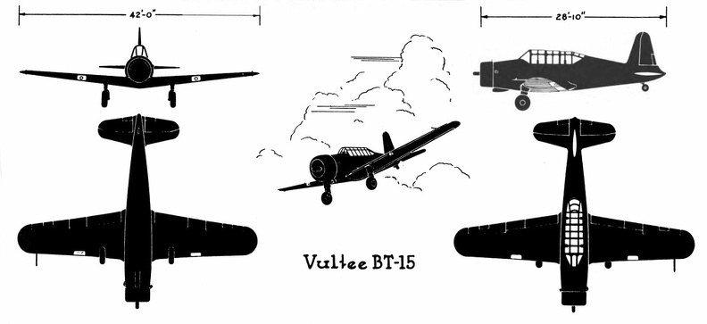 Vultee BT-15
Vultee BT-15 Front Side Perspective Bottom Top North American B-25 C & D
Front ...") North American B-25 C & D
North American B-25 C & D
North American B-25 C & D Front Side Perspective Bottom Top Vultee A-31
Front Side
...") Vultee A-31
Vultee A-31
Vultee A-31 Front Side Perspective Bottom Top Douglas C-47
Front Side
...") Douglas C-47
Douglas C-47
Douglas C-47 Front Side Perspective Bottom Top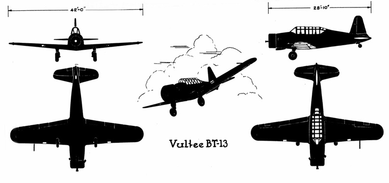 Vultee BT-13
Vultee BT-13 Front Side Perspective Bottom Top Martin B-26 B& C
Front Sid...") Martin B-26 B& C
Martin B-26 B& C
Martin B-26 B& C Front Side Perspective Bottom Top An aeroplpane in war") An aeroplpane in war
An aeroplpane in war
An aeroplpane in war Cessna AT-8
Front Side
...") Cessna AT-8
Cessna AT-8
Cessna AT-8 Front Side Perspective Bottom Top In 1678, Besnier, a French locksmith, constructed a curious flying machine consisting of two wooden ...") Besnier and his wings
Besnier and his wings
In 1678, Besnier, a French locksmith, constructed a curious flying machine consisting of two wooden bars which rested on his shoulders. At the ends of the bars he attached muslin wings, arranged to open on the down stroke and close on the up stroke. The wings were operated by moving the arms and legs. Although Besnier failed to realize that no man had sufficient muscular strength to fly as the bird flies, he did sense part of the truth—that gliding with the air currents was possible. During his experiments he is said to have jumped from a window sill, glided over the roof of a near-by cottage, and landed on a barge in the river. Douglas B-23
Front Side
...") Douglas B-23
Douglas B-23
Douglas B-23 Front Side Perspective Bottom Top The Bleriot Monoplane - top view showing its bird-like shape and the position of the pilot.") The Bleriot Monoplane - top view
The Bleriot Monoplane - top view
The Bleriot Monoplane - top view showing its bird-like shape and the position of the pilot. (1401 visits) Scouting over the ruined region between the lines (no man’s land)") Scouting over the ruined region between the lines (no man’s land)
Scouting over the ruined region between the lines (no man’s land)
Scouting over the ruined region between the lines (no man’s land) Douglas B-18A
Front Side
...") Douglas B-18A
Douglas B-18A
Douglas B-18A Front Side Perspective Bottom Top Martin B-10B
Front Side
...") Martin B-10B
Martin B-10B
Martin B-10B Front Side Perspective Bottom Top Republic P-47B
Front Side ...") Republic P-47B
Republic P-47B
Republic P-47B Front Side Perspective Bottom Top Air raid siren in Paris") Tooting the sirens of warning
Tooting the sirens of warning
Air raid siren in Paris A. Lower part of aeroplane’s hull
B. Revolving barrel to which bombs are clipped
C. Bombs
D. Re...") Bomb-releasing mechanism
Bomb-releasing mechanism
A. Lower part of aeroplane’s hull B. Revolving barrel to which bombs are clipped C. Bombs D. Releasing mechanism operated by marksman in machine. Bombs may be carried and dropped when opportunity offers; and as an improvement upon the early method, which was simply to throw these from the machine, there are releasing mechanisms now devised which carry a number of projectiles and drop them one by one as a lever is moved. The bombs, which are long, pointed, and balanced so that they will fall head first, are clipped round a barrel rather like that of a revolver, which is fixed beneath the aeroplane’s hull just below the occupants’ seat. Mechanism causes the carrying chamber to revolve and bring each bomb against a releasing catch, which—at a movement of the marksman’s lever—throws it outwards and downward. To meet the demand for a purely scouting machine, in which pilot and passenger shall have a clear fi...") Scouting Monoplane, with occupants below the wings.
Scouting Monoplane, with occupants below the wings.
To meet the demand for a purely scouting machine, in which pilot and passenger shall have a clear field for observation, both above and below, a monoplane has been designed which is called the “parasol.” This machine, a Morane-Saulnier, is shown. The two sustaining wings, forming a single surface, are raised above the body so that its occupants have nothing to impede their view earthward; and they can also see above them—an advantage of course in time of war, seeing that an enemy might be hovering overhead A. Engine and propeller B. Plane raised above hull C. Seats for pilot and passenger D. Rudder E. Elevating-plane. Plane going down in flames") Plane going down in flames
Plane going down in flames
Plane going down in flames Fairchild PT-19
Front Side...") Fairchild PT-19
Fairchild PT-19
Fairchild PT-19 Front Side Perspective Bottom Top Of famous aeroplanes at Rheims, five types stood out by themselves—the Farman, the Voisin, the Wri...") The Curtiss Biplane
The Curtiss Biplane
Of famous aeroplanes at Rheims, five types stood out by themselves—the Farman, the Voisin, the Wright, the Bleriot, and the Antoinette, all of which have been described. But there was one other, which few people had heard of before it appeared here. This was the Curtiss biplane, built by an American named Glenn H. Curtiss, and engined with a motor which also bore his name. Curtiss had experimented with many power-driven machines—motor-cycles, motor-cars, airships, and aeroplanes—and had won a prize in America with a small, light biplane, and it was a craft of this type—as seen in the figure —that he brought with him to Rheims, his idea being to compete for the speed prize. The machine had a front elevator and tail-planes, according to the practice in biplane construction; but an innovation was the setting of the ailerons midway between the main-planes—a position that will be noted in the sketch; another novelty was the way these ailerons operated. At the pilot’s back, as he sat in his driving seat, was an upright rod with two shoulder-pieces—by means of which, should he shift his body, he could swing the rod from side to side. Wires ran from the rod to the ailerons; and if the pilot leaned over, say, to the right, he drew down the ailerons on the left side of the machine. The merit of such a control was that it was instinctive; that is to say, should the biplane tip down on one side, it was natural for the pilot to lean away from the plane-ends that were sinking; and he operated the ailerons automatically, as he did this, and so brought the machine level again. A. Elevating-planes B. Pilot’s seat and control-wheel C.C. Main-planes D. Ailerons E. Motor and propeller F. Tail-plane and rudder.