


 It was called the 'Locomotion.' George Stephenson stood ready to drive it as soon as the trucks, whi...") The first Railway Journey in England
The first Railway Journey in England
It was called the 'Locomotion.' George Stephenson stood ready to drive it as soon as the trucks, which a stationary engine was lowering down the slope by means of a wire rope, had been attached to it. In the first of these trucks came the Directors of the Railway Company and their friends, followed by twenty-one trucks (all open to the sky, like ordinary goods-trucks), loaded with various passengers, and finally six more waggons of coal. Such was the first train. A man on horseback, carrying a flag, having taken up his position in front of the 'Locomotion' to head the procession, the starting word was given, and with a hiss of steam, half drowned in the shouting of the crowd, the first railway journey ever made in England was begun. When putting the car in place in the garage you must also maneuver carefully. The main thing is that...") Methods to get to the right place in a garage
Methods to get to the right place in a garage
When putting the car in place in the garage you must also maneuver carefully. The main thing is that you get in your place and as best you can. Too much brio results in broken walls and bent mudguards. If it makes you nervous, this twisting back and forth, feel free to leave it to someone else. It is not everyone's job and it is precisely with this shunting that small causes can have major consequences. [Translated online from the Dutch ] When overtaking a tram, also pay attention to the possibility that someone will jump in front of or ...") Overtaking a tram
Overtaking a tram
When overtaking a tram, also pay attention to the possibility that someone will jump in front of or from the tram. Giving a good signal and leaving as much road width as possible between the tram and your car is required. To catch up with a steam tram that hurls its plume over the road, and you it obstructs the view, it is advisable to wait until the wind chases away the steam. For the distance required to overtake a fast-moving vehicle such as a tram is too long, that the chance would not become too great that, in time, it would take to catch up with the plume of steam and drive through it. , in the meantime, a road obstruction would arise from the other side, which you would not have been able to see approaching. If you come across such a vehicle, moderate your speed so that you can stop vehicles suddenly emerging from that plume of steam. Give a strong signaland if necessary, stop the car on the right side of the road, until the tram has passed. Because then you have the most certainty, because then only a vehicle moving faster or as fast as the tram can cause danger. And this danger can be averted by giving a signal and keeping the right side of the road well. [Translated online from the Dutch ] When you stop in a street, don't forget to reach out first, as a sign for the vehicle following you....") Parking
Parking
When you stop in a street, don't forget to reach out first, as a sign for the vehicle following you. Place your car neatly along the sidewalk, not crooked or in such a way that traffic is obstructed by it. You must intervene two vehicles or cars get into the car, then drive a little further, and then reverse between the cars. Do not drive straight over to the left side of the street, against the traffic, but drive to the right and then turn along the direction of the traffic, until you are in front of the house, where you want to be. [Translated online from the Dutch ] It is also important to know, if you have to go through or along somewhere close with your car, what...") Room to pass
Room to pass
It is also important to know, if you have to go through or along somewhere close with your car, what width you need. That can become such a certainty for you that it will look like virtuosity to the uninitiated. It's a matter of routine, of course, but it can be extremely practiced. It must be started with calculating the extreme points of the fenders. Later on, even this aid is often redundant. The best way to learn this is to place two blocks of wood on the ground, or to drive two posts, which are measured just the width of the wagon apart. Riding on that is the means of learning to estimate a narrow passage. Is the width wide enough to pass, but what When measured tight, keep flat on the side of the traffic obstruction, which is on your and steering wheel side. After all, here you can see exactly how close you can get without the risk of a collision. The other side will then be free of itself. [Translated online from the Dutch ] If you have to take a side road on the right, keep your arm stretched out in horizontal direction o...") Turn Signal
Turn Signal
If you have to take a side road on the right, keep your arm stretched out in horizontal direction outside the car. [Translated online from the Dutch ] With an open torpedo, the stop signal can also be given by sticking the arm straight up. In any case...") Stop Signal
Stop Signal
With an open torpedo, the stop signal can also be given by sticking the arm straight up. In any case, account must then be taken of the somewhat higher rear of the car, or of the possibility that the passengers behind are masking the movement of the arm. [Translated online from the Dutch ] Swerving at intersections") Swerving at intersections
Swerving at intersections
Swerving at intersections Firstly, in the bends. Great tram cars, especially on narrow track, there are the annoying habit, no...") Cars and Trams
Cars and Trams
Firstly, in the bends. Great tram cars, especially on narrow track, there are the annoying habit, not far off the path of the rails to swing, including the cars of the Amsterdam-Haarlem-Zandvoort-line, the ESM Guard is in such a bend on one approaching tram, or does one want passing in the bend, a car runs the risk of being crushed or at least damaged between the rails and the curb, by the swinging front or rear upper part of the car. [Translated online from the Dutch ] Lady driving in a horse and cart") Lady driving in a horse and cart
Lady driving in a horse and cart
Lady driving in a horse and cart A Chinese sedan chair and bearers") A Chinese sedan chair and bearers
A Chinese sedan chair and bearers
A Chinese sedan chair and bearers While in Paris, President Yerkes, of the North Chicago Street Railway Company, purchased a noiseless...") A Steam Street Railway Motor
A Steam Street Railway Motor
While in Paris, President Yerkes, of the North Chicago Street Railway Company, purchased a noiseless steam motor, the results in experimenting with which will be watched with great interest. The accompanying engraving, for which we are indebted to the Street Railway Review, gives a very accurate idea of the general external appearance. The car is all steel throughout, except windows, doors, and ceiling. It is 12 ft. long, 8 ft. wide, and 9 ft. high, and weighs about seven tons. The engines, which have 25 horsepower and are of the double cylinder pattern, are below the floor and connected directly to the wheels. The wheels are four in number and 31 in. in diameter. The internal appearance and general arrangement of machinery, etc., is about that of the ordinary steam dummy. It will run in either direction, and the exhaust steam is run through a series of mufflers which suppress the sound, condense the steam and return the water to the boiler, which occupies the center of the car. The motor was built in Ghent, Belgium, and cost about $5,000, custom house duties amounting to about $2,000 more. There needs to be an equipment of spare machines also; and a number of travelling workshops with ski...") Travelling workshop for the repair of military aeroplanes
Travelling workshop for the repair of military aeroplanes
There needs to be an equipment of spare machines also; and a number of travelling workshops with skilled engineers, which can be rushed from place to place for the repair of damaged craft. A sketch of one of these workshops on wheels, which are vital to the organisation, is seen in the figure We present a bicycle for ladies, lately invented and patented by Messrs. Pickering & Davis of New Yo...") Velocipede for Ladies
Velocipede for Ladies
We present a bicycle for ladies, lately invented and patented by Messrs. Pickering & Davis of New York City. It will be seen that the reach or frame, instead of forming a nearly straight line from the front swivel to the hind axle, follows the curve of the front wheel until it reaches a line nearly as low as the hind axle when it runs horizontally to that point of the hind wheel. The two wheels being separated three or four inches, allow of an upright rod being secured to the reach; around this is a spiral spring, on which a comfortable, cane-seated, willow-backed chair is placed. This machine, with a moderate-sized wheel (of thirty to thirty-three inches), will allow being driven with a great deal of comfort and all the advantages of the two-wheel veloce. In mounting, a lady has to step over the reach, at a point only twelve inches from the floor, the height of an ordinary step in a flight of stairs. We present an engraving of an English one-wheeled velocipede. The feet are placed on short stilts, c...") English one-wheeled Velocipede
English one-wheeled Velocipede
We present an engraving of an English one-wheeled velocipede. The feet are placed on short stilts, connected with the cranks, one on either side of the rim, while the rider sits upon a steel spring saddle over the whole wheel. The inventor modestly limits the diameter of the wheel to twelve feet, and the number of revolutions to fifty per minute. Twenty-five miles per hour is the speed expected to be reached. The riders of this machine, without the ability to overcome the laws of gravity, would be very likely to get broken bones and noses. It is not likely to come into general use. HEMMING'S UNICYCLE, or \"FLYING YANKEE VELOCIPEDE.\"
The single-wheeled velocipede has at length ...") Flying Yankee Velocipede
Flying Yankee Velocipede
HEMMING'S UNICYCLE, or "FLYING YANKEE VELOCIPEDE." The single-wheeled velocipede has at length received a palpable body, and " a local habitation and a name." Richard C. Hemming of New Haven, Conn., invented the machine herewith represented, two years ago; but has only recently brought it into the market and applied it to practical purposes.. The main wheel has a double rim, or has two concentric rims, the inner face of the inner one having a projecting lip for keeping the friction rollers and the friction driver in place; each of these being correspondingly grooved on their peripheries. The frame on which the rider sits, sustains these friction wheels in double parallel arms, on the front one of which is mounted a double pulley, with belts passing to small pulleys on the axis of the driving wheel. This double wheel driven, as seen, by cranks turned by the hands. The friction of the lower wheel on the surface of the inner rim of the main wheel is the immediate means of propulsion. A small binding wheel, seen between the rider's legs, serves to keep the bands or belts tight. The steering is effected either by inclining the body to one side or the other, or by the foot impinging on the ground, the stirrups being hung low for this purpose. By throwing the weight on these stirrups, the binding wheel may be brought more powerfully down on the belts. Over the rider's head is an awning, and there is also a shield in front of his body to keep the clothes from being soiled by mud and wet. When going forward, the driving wheel is kept slightly forward of the centre of gravity by the position of the rider. By this means the power exerted is comparatively small. Every turn of the crank is equivalent to a rotation of the great wheel. Mr. Hemming says that this machine can be manufactured for fifty dollars, of a weight of only thirty pounds;- that it will ascend steep grades, and that it can be driven on the roads with but little exertion, at the rate of twenty or even twenty-five miles an hour. This wheel is of a diameter of from six to eight feet. Mr. Hemming's boy of thirteen has one five feet in diameter, the first manufactured, crude in construction, and heavier than necessary, which he propels at the rate of a mile in three minutes.
This velocipede was patented January 5th, 1869. It has been thoroughly tested and is pronounced a ...") Callihan's Velocipede
Callihan's Velocipede
This velocipede was patented January 5th, 1869. It has been thoroughly tested and is pronounced a complete success. It will be seen that it is very different from Bradford's machine. The front wheels are used as guiding wheels, the rear as the driving ones. It is propelled by both hands and feet, acting together or separately. The propelling power is almost unlimited, and is furnished by cranks in the hind axles, with lever attachments. It has three different steering arrangements, either of which can be applied, according to the taste of the purchaser. In all these, the forward wheel and axle are turned with a lever arrangement, operated upon by the band. The machine develops both chest and limbs, and can be readily used by ladies and children. A little girl of six years has ridden it for an hour without fatigue. It is so constructed, that scruples of delicacy need prevent no lady from driving it. It can be driven either backwards or forwards, will run upon the road, at the rate of fifteen miles an hour, and will ascend any ordinary hill with ease. It is claimed, that it is the only machine made that can be checked in going down hill, or that can be stopped instantly. The machine varies in size and weight. That most in favor, has a wheel of three feet and a half in diameter, and a weight of about one hundred pounds. It is constructed of the best material, and is neat and nobby in appearance. Its price is $125. If any of our readers desire the luxury of a ride on a velocipede without the necessity of taking le...") Bradford's Velocipede
Bradford's Velocipede
If any of our readers desire the luxury of a ride on a velocipede without the necessity of taking lessons, or the danger of getting a fall, they will find " Bradford's Four-Wheeled Velocipede" ready and able to afford them the pleasure. The inventor of this vehicle, Mr. C. K. Bradford, has devoted the greater part of the last five years to experiments upon the velocipede, and took out his first patent three years and a half ago. The machine, as now constructed and improved, obtained its American patent October 13th, 1868. It has since been patented in England, France, and Belgium. It is made of the best material, and finished like a gentleman's trotting wagon. It weighs but sixty-five pounds, and combines in a high degree both lightness and strength. Any man, woman or child, can learn to guide it easily with but a few moments practice. The inventor claims that it is able to maintain a speed of a mile in three minutes, and that the extraordinary time of a half mile in one minute and forty-five seconds, has been made upon a country road. It can be driven by almost any man, at the rate of a mile in four minutes, on almost any road, without greater exertion than is ordinarily used in walking. This velocipede, unlike all others, is seen to best advantage on the street. In Mr. Bradford's tasteful little curricle, the rider can sit at ease as carelessly as in a carriage, giving himself up wholly to the exhilaration of the rapid movement, and the pleasurable exercise of the muscles, which is just enough to make the machine skim over the ground, and give an enjoyable sense of power. The increase of friction, which would naturally result from the additional number of wheels, is prevented by an application of anti-friction rollers, which reduce the labor of propelling the machine to a minimum, a requisite of the highest importance to a person seeking either recreation or utility. As will be seen from the accompanying engraving, \"Pickering's American Velocipede,\" manufactured by ...") Pickering's American Velocipede
Pickering's American Velocipede
As will be seen from the accompanying engraving, "Pickering's American Velocipede," manufactured by Messrs. Pickering & Davis, differs very materially from the French model, so generally used by other manufacturers. It is claimed that it is more simple and durable, lighter and stronger. The reach or frame of this velocipede is made of hydraulic tubing. The gun-metal bearings are so attached that, when worn, they may be replaced by others, which are interchangeable like the parts of sewing-machines and fire-arms. The axle is so constructed as to constitute, in itself, an oil box. It is made tubular, and closed at either end with a screw, on the removal of which it is filled with lard oil. Cotton lamp-wick is placed loosely in the tubular axle and the oil is by this means fed to the bearing, as fast as required, through the small holes made for the purpose in the centre of the axle. The saddle is supported on a spiral spring, giving an elastic seat; it is brought well back, so that the rider maintains an erect position, and is adjustable to suit the length of limb of the rider. The tiller or steering handle is constructed with a spring so that the hands are relieved from the jolting that they would otherwise receive while running over rough ground. The stirrups or crank pedals, are three-sided, with circular flanges at each end, fitted to turn on the crank pins, so that the pressure of the foot will always bring one of the three sides into proper position. They are so shaped as to allow of the use of the forepart of the foot, bringing the ankle joint into play, relieving the knee, and rendering propulsion easier than when the shank of the foot alone is used. The connecting apparatus differs from that of the French vehicle in that the saddle bar serves only as a seat and brake, and is not attached to the rear wheel. By a simple pressure forward against the tiller, and a backward pressure against the tail of the saddle, the saddle spring is compressed, and the brake attached to it brought firmly down against the wheel. Messrs. Pickering & Davis have a large manufactory, and are the constant recipients of orders from all parts of the country. Mr. Pickering has always been a practical machinist, and personally superintends the structure of each machine turned out.
The accompanying engraving will convey to the mind of the reader a correct idea of the French two-...") Construction of the Bicycle
Construction of the Bicycle
The accompanying engraving will convey to the mind of the reader a correct idea of the French two-wheeled velocipede. The majority of makers in this country fashion their machine upon this pattern in every essential respect. We append a full technical description. A is the front wheel. This is the steering wheel, and upon its axis, the power is applied. B is the hind wheel; C, the treadles or foot-pieces ; D, the treadle cranks; E, slots in cranks, by which to adjust the foot-pieces and accommodate the length to the legs of the rider; F, bifurcated jaw, the lower part of which forms the bearing for the axle of the front wheel. From the upper part of this jaw, a rod or pivot extends, to which is attached the steering arm or handle F; G, the reach or perch, extending from the jaw of the front wheel to the rear or hind wheel. This reach is bifurcated, forming jaws for the hind wheel. H, " rests" on the front part of the reach. The rider puts one leg on the rest and works one of the cranks with the other leg while riding " side-saddle," or a leg may be placed upon each rest when the velocipede has acquired sufficient momentum, and the rider does not wish to keep his feet upon the treadles. I, the saddle or seat, which is adjustable on the seat-spring L, by the thumb-screw K. The seat-spring L, is attached at M to the reach G, which, at the other end, is fastened to the spring-struts N, that rise from the reach G; 0, the brake-lever, on the fulcrum P; Q,, the " shoe " of the brake that acts against the periphery of the hind wheel. The brake is operated by means of the cord S, one end of which is attached to the steering handle F, and the other end to the reach at 3. A cord passes from the steering handle under the pulley or roller 4, thence over the pulley 5, on the brake-lever 0, and from there to the point 3, where it is attached to the reach G. The brake is operated by giving a slight turning motion to the handle F, thus winding a small sheave upon the axis of the handle, and bring-ing the shoe Q, of the brake-lever 0, in contact with the surface of the wheel B. Of the various kinds of velocipedes, four, three, two, and one wheeled, the bicycle seems to be cons...") The Bicycle
The Bicycle
Of the various kinds of velocipedes, four, three, two, and one wheeled, the bicycle seems to be considered the most artistic, is altogether the most in favor, and steadily maintains its ground against all rivals. Whether it will be the model velocipede of the future remains to be seen. The various experiments now being tried will, no doubt, eventually result in a nearly perfect machine, but it will require a season's experience fully to develop the ingenuity of our American artisans. Many have expressed doubts as to the real utility of the velocipede, and the permanency of its use. They seem to think it a frivolous invention only calculated to serve purposes of amusement, and soon to be superseded by some other ephemeral claimant for popularity. Most of these have based their opinions upon the disuse into which rude machines have fallen in former times. But the difference in the construction of the modern velocipede from the primitive one has entirely changed the character of the vehicle. It is no longer a draft vehicle, but a locomotive, and as much superior to the original bar on wheels, as the improved steam locomotive is to the old-time stage-coach. Drasina
This novel vehicle, under the name of \" Drasina was introduced into England in 1818, and, a...") Drasina
Drasina
Drasina This novel vehicle, under the name of " Drasina was introduced into England in 1818, and, at first, the greatest possible expectations were created, with regard to its usefulness and speed. It was maintained, that it would travel up-hill on a post-road as fast as a man could walk ; that on a level, even after a heavy rain, it would average six or seven miles an hour ; and that, on a descent, it would equal a horse at fall speed. It was described in the advertisements of the day as " consisting of two wheels, one behind the other, connected by a perch, on which a saddle is placed as a seat. The front wheel is made to turn on a pivot, guided by a circular lever or rudder, which comes op to the hand; the fore-arms rest on a cushion in front ; in this position, both hands holding the rudder firmly, the machine and traveller are preserved in equilibrio. In 1821 Lewis Gomperta of Surrey, introduced some decided improvements upon the Drasina , as will be seen from the accompanying engraving. The object of the improvement of Gomperta was to bring the arms of the rider into action, in assist-ance to his legs. It consisted " in the application of a handle, C, which is to be worked backwards and forwards, to which is attached a circular rack, D G, which works in a pinion, E, with ratch wheel on the ont wheel of the velocipede, and which, on being pulled by the rider with both hands, sends the machine forward; and when thrust from him does not send it back again, on account of the ratch, which allows the pinion to turn in that direction, free of the wheel. H is the saddle, and the rest, B is so made that the breast of the rider bears against it, while the sides come around him at some distance below the arms, and is stuffed." The rider could with this machine either propel it entirely without the feet, or he could use the feet, while the arms were free. The beam, A, was made of beech wood, and a pivot at F, allowed the front wheel to be turned to the right or left at the will of the rider. The article upon the Velocipede in the \" American Encyclopedia,\" commences by giving the well-known ...") Velocipedes
Velocipedes
The article upon the Velocipede in the " American Encyclopedia," commences by giving the well-known derivation of the word from the Latin velox, swift, and pes, a foot, and defines it as a carriage, by means of which the rider propels himself along the ground, and states that it was invented at Manheim.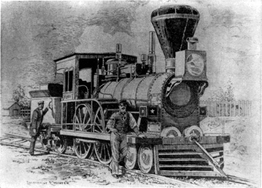 The Fury
The “Fury,” built for the Boston and Worcester Railroad in 1849 by Wilmarth. It was known as a “Shanghai” because of its great height. Diagram comparing the Pioneer (shaded drawing) with the Columbia, a standard 8-wheel engine of 1851....") Diagram comparing the Pioneer with the Columbia
Diagram comparing the Pioneer with the Columbia
Diagram comparing the Pioneer (shaded drawing) with the Columbia, a standard 8-wheel engine of 1851. (Drawing by J. H. White.) Columbia Hudson River Railroad Lowell Machine Shop, 1852 Wt. 271/2 tons (engine only) Cyl. 161/2 x 22 inches Wheel diam. 84 inches Pioneer Cumberland Valley Railroad Seth Wilmarth, 1851 121/2 tons 81/2 x 14 inches 54 inches “Pioneer” locomotive. (Drawing by J. H. White.)") Pioneer Locomotive
Pioneer Locomotive
“Pioneer” locomotive. (Drawing by J. H. White.) “Pioneer” locomotive,
(1) Safety valve,
(2) spring balance,
(3) steam jet
(4) dry pipe
(5...") Pioneer Locomotive
Pioneer Locomotive
“Pioneer” locomotive, (1) Safety valve, (2) spring balance, (3) steam jet (4) dry pipe (5) throttle lever (6) throttle (7) crown bar (8) front tube sheet (9) check valve (10) top rail (11) rear-boiler bracket (12) pedestal (13) rocker bearing (14) damper (15) grate (16) bottom rail (17) pump heater valve (18) cylinder lubricator (19) reversing lever (20) brake shoe (21) mud ring (22) blowoff cock (23) ashpan (Drawing by J. H. White.) “Pioneer” locomotive. (1) Air chamber, (2) reversing lever, (3) counterweight, (4) reversing sha...") Pioneer Locomotive
Pioneer Locomotive
“Pioneer” locomotive. (1) Air chamber, (2) reversing lever, (3) counterweight, (4) reversing shaft, (5) link hanger, (6) rocker, (7) feedwater line to boiler, (8) link block, (9) link, (10) eccentric, (11) pump plunger, (12) pump steamheater line, (13) feedwater pump, (14) wire netting [bonnet], (15) deflecting cone, (16) stack, (17) stack hopper. (Drawing by J. H. White.) Rear elevation of Pioneer and detail of valve shifter; valve face and valve. (Drawing by J. H. White...") Rear elevation of Pioneer
Rear elevation of Pioneer
Rear elevation of Pioneer and detail of valve shifter; valve face and valve. (Drawing by J. H. White.)
Patent Iron Suspension Railroad Bridge.
The undersigned would inform the officers of Railroads ...") Wendell Bollmans Patent Bridge
Wendell Bollmans Patent Bridge
Patent Iron Suspension Railroad Bridge. The undersigned would inform the officers of Railroads and others, that he is prepared to furnish Drawings and Estimates for Bridges, Roofs, etc., on the plan of Bollman’s Patent. The performance of these bridges, some of which have been in use for six years, has given entire satisfaction. Their simplicity of construction renders repairs easy and cheap, and by a peculiar connection of the Main and Panel Rods at the bottom of the Posts, all danger from the effects of expansion, which has heretofore been the chief objection to Iron Bridges, is entirely removed. J. H. TEGMEYER, Baltimore, Md. Shortly after the Harpers Ferry bridge reconstruction, Bollman was made foreman of bridges. It is ap...") Plan of Harpers Ferry Bridge
Plan of Harpers Ferry Bridge
Shortly after the Harpers Ferry bridge reconstruction, Bollman was made foreman of bridges. It is apparent that, on the basis of his practical ability, enhanced by the theoretical knowledge gained by intense self-study, he eventually came to assist Chief Engineer Benjamin H. Latrobe in bridge design. He later took this work over entirely as Latrobe’s attentions and talents were demanded in the location and extension of the line between Cumberland and Wheeling. Description of first trip in the car
When I got this car ready to run one night, I took it out a...") Duryea Automobile
Duryea Automobile
Description of first trip in the car When I got this car ready to run one night, I took it out and I had a young fellow with me; I thought I might need him to help push in case the car didn't work…. We ran from the area of the shop where it was built down on Taylor Street. We started out and ran up Worthington Street hill, on top of what you might call "the Bluff" in Springfield. Then we drove along over level roads from there to the home of Mr. Markham , and there we refilled this tank with water. [At this point he was asked if it was pretty well emptied by then.] Yes, I said in my account of it that when we got up there the water was boiling furiously. Well, no doubt it was. We refilled it and then we turned it back and drove down along the Central Street hill and along Maple, crossed into State Street, dropped down to Dwight, went west along Dwight to the vicinity where we had a shed that we could put the car in for the night. During that trip we had run, I think, just about six miles, maybe a little bit more. That was the first trip with this vehicle. It was the first trip of anything more than a few hundred yards that the car had ever made. It can be readily seen that this drawing was not made after the plan of the first vehicle.") A drawing and the first page of the specifications of the first patent issued to C. E. Duryea
A drawing and the first page of the specifications of the first patent issued to C. E. Duryea
It can be readily seen that this drawing was not made after the plan of the first vehicle. Drawing of 1885 Benz engine, showing
similarity in general appearance to Duryea engine. From
Karl ...") Drawing of 1885 Benz engine
Drawing of 1885 Benz engine
Drawing of 1885 Benz engine, showing similarity in general appearance to Duryea engine. From Karl Benz und sein Lebenswerk, Stuttgart, 1953. (Daimler-Benz Company publication.) Phantom illustration of Benz' first automobile.
(From Carl Benz, Father of the Automobile Industry,...") Phantom illustration of Benz' first automobile
Phantom illustration of Benz' first automobile
Phantom illustration of Benz' first automobile. (From Carl Benz, Father of the Automobile Industry, by L. M. Fanning, New York, 1955.) Illustration from U.S. patent 385087,
issued to Carl Benz, showing the horizontal plane
of the fly...") Illustration from U.S. patent 385087
Illustration from U.S. patent 385087
Illustration from U.S. patent 385087, issued to Carl Benz, showing the horizontal plane of the flywheel, a feature utilized by the Duryeas in their machine. Chauffeur driving two ladies") Chauffeur driving two ladies
Chauffeur driving two ladies
Chauffeur driving two ladies Chauffeur opening door for a lady") Chauffeur opening door for a lady
Chauffeur opening door for a lady
Chauffeur opening door for a lady The 8 h.p. twin cylinder Uni, with wheel steering and free engine. The power plant slides upon rails...") A Possibility of Motorcycling in the Future
A Possibility of Motorcycling in the Future
The 8 h.p. twin cylinder Uni, with wheel steering and free engine. The power plant slides upon rails at the rear platform by means of a cable actuated from the lever beside the driver The 16 h.p. Uni-motorcycle, with spring suspension, magneto ignition, free engine and wheel steering...") A Possibility of Motorcycling in the Future
A Possibility of Motorcycling in the Future
The 16 h.p. Uni-motorcycle, with spring suspension, magneto ignition, free engine and wheel steering. Car driving by horses on the road") Driving on the road
Driving on the road
Car driving by horses on the road Automobile Driver") Automobile Driver
Automobile Driver
Automobile Driver In 1830 all this had disappeared, and we find in Mr. Nasmyth's sketch a regular fire-box, such as is...") The Rocket 1830
The Rocket 1830
In 1830 all this had disappeared, and we find in Mr. Nasmyth's sketch a regular fire-box, such as is used to this moment. In one word, the Rocket of 1829 is different from the Rocket of 1830 in almost every conceivable respect; and we are driven perforce to the conclusion that the Rocket of 1829 never worked at all on the Liverpool and Manchester Railway; the engine of 1830 was an entirely new engine. We must remember that travelling was no such simple and easy matter then as it is now. As the plante...") Washington's Coach
Washington's Coach
We must remember that travelling was no such simple and easy matter then as it is now. As the planters in Virginia usually lived on the banks of one of the many rivers, the simplest method of travel was by boat, up or down stream. There were cross-country roads, but these at best were rough, and sometimes full of roots and stumps. Often they were nothing more than forest paths. In trying to follow such roads the traveler at times lost his way and occasionally had to spend a night in the woods. But with even such makeshifts for roads, the planter had his lumbering old coach to which, on state occasions, he harnessed six horses and drove in great style. A Stage Coach of the Eighteenth Century") A Stage Coach of the Eighteenth Century
A Stage Coach of the Eighteenth Century
A Stage Coach of the Eighteenth Century The Dandy-horse of 1818, the two wheels on which the rider sat astride, tipping the ground with his ...") The Dandy-horse
The Dandy-horse
The Dandy-horse of 1818, the two wheels on which the rider sat astride, tipping the ground with his feet in order to propel the machine, was laughed out of existence.") 1910 New Engines
1910 New Engines") Sidecar
Sidecar") Yale 1910
Yale 1910") Parts of a motorbike
Parts of a motorbike (872 visits)") Parts of a motorbike (2)
Parts of a motorbike (2)") 1910 Curtis
1910 Curtis") LA Motordrome
LA Motordrome") Gibbs Electric Truck
Gibbs Electric Truck") Woods Brougham
Woods Brougham") Tudor Knox
Tudor Knox") Twenty-Passenger Break for the World's Fair
Twenty-Passenger Break for the World's Fair") White Steamer
White Steamer") The Winton
The Winton") The Wolverine
The Wolverine