


Home / Albums / Search results 642
Choose filters
Cancel
Validate
Choose filters
Validate
Validate
Validate

 This ship shows the new sail plan overcoming the old. The masts carry topsails,
topgallantsails, a...") A Corvette of 1780
A Corvette of 1780
This ship shows the new sail plan overcoming the old. The masts carry topsails, topgallantsails, and royals, and what was formerly a lateen sail on the mizzenmast has become a spanker. Furthermore, while the ship carries jibs, she has not yet parted with her spritsails. A British warship of 1654. This ship is an excellent example of the ships that were in use just befo...") The Amaranthe
The Amaranthe
A British warship of 1654. This ship is an excellent example of the ships that were in use just before the jib began to put in its appearance. The lateen sail on the mizzenmast is similar to the one used on the caravels, but both the rigging and the hull are greatly refined as compared with the ships of the time of Columbus. Which, with the Fiery Cross, Taeping, Serica, and Taitsing, sailed what was, perhaps, the greatest r...") The Ariel, 1866
The Ariel, 1866
Which, with the Fiery Cross, Taeping, Serica, and Taitsing, sailed what was, perhaps, the greatest race ever run. After sailing 16,000 miles from Foo-Chow, China, to London, the Ariel, Taeping, and Serica docked in London on the same tide, the Taeping the winner by only a few minutes. The other two were only two days behind, although the first three took 99 days. Square-rigged ships have largely disappeared because, among other things, their crews were large.
T...") An American Coasting Schooner
An American Coasting Schooner
Square-rigged ships have largely disappeared because, among other things, their crews were large. These schooners, which sometimes have four or five masts, can be handled by small crews and consequently are able to continue to vie with steam. Biplane (541 visits) A. Hull, which is steel-built, containing pilot and passenger
B. Main-planes—the lower at a dihed...") D.F.W. (German-designed) Biplane
D.F.W. (German-designed) Biplane
A. Hull, which is steel-built, containing pilot and passenger B. Main-planes—the lower at a dihedral angle C. Uptilted stabilising ailerons, which may be locked in position D. Stabilising fin E. Rudder F. Elevating-plane G. 100-h.p. motor (which is enclosed) and propeller. The greatest clipper ship ever built. Unfortunately, before she made her first voyage she caught fir...") The Great Republic
The Great Republic
The greatest clipper ship ever built. Unfortunately, before she made her first voyage she caught fire and had to be sunk. She was refloated and refitted, but never made a voyage in her original rig. When new masts were put in her they were made smaller than the first ones. Still she turned out to be one of the very fastest of the clippers.") Royal Mail Coach
Royal Mail Coach An awkward and unsuccessful ship.
She proved, however, when she was wrecked, that for ship constru...") The Great Britain
The Great Britain
An awkward and unsuccessful ship. She proved, however, when she was wrecked, that for ship construction iron is stronger than wood, and proved, too, that double bottoms, bulkheads, and bilge keels, which were new departures when she was built, were most desirable in ships of her size.") A 'Fischer' Combination Omnibus
A 'Fischer' Combination Omnibus") A type of extemporised motor ambulance favoured by the French and Belgians
A type of extemporised motor ambulance favoured by the French and Belgians The fitting of several motors has been shown to be practical; and it has the obvious advantage that,...") Multiple-engined craft
Multiple-engined craft
The fitting of several motors has been shown to be practical; and it has the obvious advantage that, should one fail while in the air, the other or others will maintain a craft in flight. In such a machine as would fly the Atlantic, for example, it is proposed to fit four motors developing 800 h.p., and to carry a couple of mechanics who would constantly be tending them. Thus, should one engine develop trouble, its repair could be effected without descent, and with no worse result than a temporary fall in speed. In the figure is shown a method by which three Gnome motors may be fitted to a biplane. A. First engine (a 50-h.p. Gnome) B. Second engine (which is on the same shaft, but will run independently) C. Third Gnome engine, also an independent unit D. Four-bladed propeller (mounted higher than the crank-shaft bearing the engines, and driven by a chain gearing).") Driving-seat of a touring plane
Driving-seat of a touring plane This ship may be said to be the first of the transatlantic liners,
for in her, for the first time,...") The Steamship Oceanic
The Steamship Oceanic
This ship may be said to be the first of the transatlantic liners, for in her, for the first time, great concessions were made for the comfort and convenience of the passengers. A. Enclosed body
B. Driver’s position
C. Steering wheel
D. Foot-controlled throttle lever for e...") The single-seated 'air-car'—a suggested type
The single-seated 'air-car'—a suggested type
A. Enclosed body B. Driver’s position C. Steering wheel D. Foot-controlled throttle lever for engine E.E. The two sustaining-planes F. The motor G. Propeller H. Rudder I. Elevating-plane J. Landing gear. First probably for mails, and after this for passenger-carrying, will aeroplanes of the future be employed; and they will find a scientific use, too, in exploring remote corners of the earth, and in passing above forests which are now impenetrable. Small, fast machines, much cheaper than those of to-day, will be bought also for private use—many of them, as suggested by the figure, having room for only one man within their hulls. Then there will be flying clubs; and to these, after their day’s work, will come a city’s toilers. Through the cheapening of craft, as time goes on, practically all members of the community will experience the joys of flight. Thus, say on a summer’s evening, the doors of the sheds will be pushed aside, and the machines wheeled out and overhauled; then, one by one, these small, fast-moving craft will rise into the air and dart here and there—circling, manœuvring, dipping, and diving.") Space Shuttle - port elevation
Space Shuttle - port elevation How lightly a petrol engine can be made was demonstrated by the firm constructing the Antoinette mo...") Man lifting a 100 horse-power aeroplane motor
Man lifting a 100 horse-power aeroplane motor
How lightly a petrol engine can be made was demonstrated by the firm constructing the Antoinette motor, with which many of the pioneers fitted their craft. A 16-cylinder engine was made so that a man could raise it upon his shoulders—as shown in Figure —and carry it without much difficulty; and yet this same motor, which one man could lift from the ground, developed 100 horse-power.") Banked turn on a biplane
Banked turn on a biplane") Space Shuttle - isometric
Space Shuttle - isometric When the Wrights had built an engine, there was still the question how they should make it drive the...") Wright Motor and Propellers
Wright Motor and Propellers
When the Wrights had built an engine, there was still the question how they should make it drive their aeroplane. They inclined naturally to the idea of an aerial propeller. Two courses lay open to them; they could fit one propeller running at high speed and coupled directly to the motor, or they could use two propellers, revolving at slower speed and geared in some way to the engine. They decided upon the latter course, placing two propellers behind the main planes of their machine and driving them from the engine by means of light chains, these running in guiding tubes. This system of propulsion is shown. A. Motor; B. Gear-wheels upon motor crank-shaft; C.C. Tubes carrying driving chains; D.D. Sprocket-wheels over which chains pass; E.E. Propellers., 1750 (622 visits)") Travelling Posting Carriage (2), 1750
Travelling Posting Carriage (2), 1750 Lilienthal was fascinated by the mechanism of the bird’s wing. He and his brother built one machin...") Lilienthal's Experiments
Lilienthal's Experiments
Lilienthal was fascinated by the mechanism of the bird’s wing. He and his brother built one machine after another to determine the exact amount of lifting effort that a man could obtain by imitating the wing-beat of a bird. One such apparatus is illustrated. This had a double set of wings; a wide pair in the centre and narrower ones in front and at the rear. These wings beat alternately, by movements of the operator’s legs; and the machine was suspended by a rope and pulleys from a beam, being counterbalanced by a weight. The tests showed this: that, after some practice in working the wings, a man could raise with them just half the weight of himself and of the machine; but the muscular effort proved so great that he could only maintain this rate of wing-beating for a few seconds. Here, incidentally, a fact may be mentioned: the energy a man can produce, at all events for a prolonged effort, has been estimated at about a quarter of a horse-power; and this—in tests so far made—has been insufficient for the purpose of wing-flapping flight. The engines drove two canvas-covered wooden screws, each 18 feet in length, and the general appearan...") The Maxim Machine
The Maxim Machine
The engines drove two canvas-covered wooden screws, each 18 feet in length, and the general appearance of the machine is indicated by the picture. In these trials, although it was always captive, the aeroplane demonstrated much that its inventor had set himself to prove. In Sir Hiram Maxim’s own words, it showed that it had “a lifting effect of more than a ton, in addition to the weight of three men and 600 lbs. of water.” He adds: “My machine demonstrated one very important fact, and that was that very large aeroplanes had a fair degree of lifting power for their area.” Hence there is a type of fast scouting monoplane, in which a pilot can ascend alone, and fly at 100 ...") Single-seated Air Scout
Single-seated Air Scout
Hence there is a type of fast scouting monoplane, in which a pilot can ascend alone, and fly at 100 miles an hour. With such a craft, sweeping rapidly above an enemy’s position, the pilot-observer can return with his information at surprising speed. In the figure an air-scout of this type is seen. The tapering, covered-in body will be observed; this is to reduce wind resistance as the machine rushes through the air. The Gnome engine is, for the same reason, covered by an aluminium shield, which only allows the lower cylinders to project; they must, of course, be exposed in some way to the air, or they would not cool themselves. The landing-carriage has been reduced to its simplest form; this, again, is to reduce wind resistance; and the pilot, sitting deep in the body, shows only his head as the machine flies. Here, again, apart from the greater comfort in being so shielded, the placing of the pilot within the machine spells a lessening of pressure. A. Propeller B. Motor (partly hidden by shield) C. Pilot’s seat D. Sustaining plane E. Rudder F. Elevating-plane G. Chassis. One of the first to work upon Sir George Cayley’s theories was an experimenter
named Henson. H...") Henson's Proposed machine
Henson's Proposed machine
One of the first to work upon Sir George Cayley’s theories was an experimenter named Henson. He planned an ambitious machine weighing about a ton. It was to have planes of canvas stretched over a rigidly trussed frame of bamboo rods and hollow wooden spars; and these planes were to contain 4500 square feet of lifting surface, and be driven by screws operated by a steam engine of 30 h.p. But this craft did not take practical shape, although in its appearance and many of its details it bore a resemblance to machines which ultimately were to fly. In the specification of the patent he took out for his invention, Henson indicated that it was for “Improvements in locomotive apparatus and machinery for conveying letters, goods, and passengers from place to place through the air.” There is a type of aeroplane which will be carried to sea when a fleet sails, stowed in sections wit...") Launching sea-planes from a ship’s deck
Launching sea-planes from a ship’s deck
There is a type of aeroplane which will be carried to sea when a fleet sails, stowed in sections within the hull of a transport ship. This machine—a light, high-speed craft—will be assembled upon the deck of its parent ship, and launched into the air by special mechanism, as there is not room for a machine to run upon wheels, and leave the ship’s deck as it might do upon land; the vessel, besides, might be rolling in a high sea. In some cases a platform is built upon the deck, either at the bow or stern, and along this the aircraft moves, so as to gain speed for its planes to lift. In one device, seen in Figure, the machine is mounted upon a light wheeled cradle, and this is placed upon the starting-rail. Then, driven by its propeller, the plane runs forward upon the cradle till it reaches the end of the rail, when it glides into the air, the cradle falling from it and dropping into the sea, from which it is retrieved and drawn back on board the ship. The sea-plane (A.) is seen taking flight, having glided upon its cradle along the platform (B.). The cradle (C.) is just falling away below the aircraft’s hull. Henson and Stringfellow built in 1845 a model which weighed about 30 lbs.; and although its stabilit...") Henson and Stringfellow’s Model
Henson and Stringfellow’s Model
Henson and Stringfellow built in 1845 a model which weighed about 30 lbs.; and although its stability was not perfect, it was an interesting machine—a forecast of the monoplane of the future. Here one saw the lifting planes take shape; the body between the wings; the tail-planes at the rear; and, above all, a suggestion of the means by which machines would be driven through the air: the fitting to the model, that is to say, of revolving propellers or screws. When an inventor has fitted an engine to an aircraft, means must be devised for using its power to drive the machine through the air; and to make the wings flap like those of a bird, has been found so complicated, owing to the mechanism necessary to imitate natural movements, that much of the power is wasted. Inventors such as Henson and Stringfellow, realising this difficulty, made wings that were outstretched and immovable, like those of a bird when it is soaring, and relied upon screw propellers—which they set spinning at great speed by means of their engines—to thrust their craft forward through the air. One of the men who thus laboured, without himself seeing his work brought to the goal of success, wa...") Langley’s Steam-driven Model
Langley’s Steam-driven Model
One of the men who thus laboured, without himself seeing his work brought to the goal of success, was Professor S. P. Langley, an American scientist connected with the Smithsonian Institution, and a man of original ideas and great resource. He made a methodical investigation of the action of lifting planes and the shape of propellers, using a large revolving table so that he could test the latter while they were moving through the air. Then he began building models which took a double monoplane form, as indicated in picture, with wings set at dihedral or upturned angle. This uptilting of the wings was to give the models stability while in flight: and the fixing of planes at the dihedral angle was tested, by later experimenters, in regard to full-sized machines. A method of flying was suggested as long ago as 1744, by the inventor De Bacqueville; his plan was ...") De Bacqueville
De Bacqueville
A method of flying was suggested as long ago as 1744, by the inventor De Bacqueville; his plan was to fix four planes or wings to his hands and feet, and then propel himself through the air by vigorous motions of his arms, and kickings of his legs. He made a flight from a balcony overlooking a river, but finished his trial ingloriously by falling into a barge. Such schemes, indeed, were doomed to failure; and they are only interesting because they show how, even in those far-off days, men were ready to risk their lives in attempts to conquer the air.") Travelling Post, 1825-35
Travelling Post, 1825-35") Space Shuttle - forward and Adt elevations
Space Shuttle - forward and Adt elevations Phillips built the strange-looking machine. It resembled, more than anything else, a huge Venetian b...") Phillips’s Experimental Craft
Phillips’s Experimental Craft
Phillips built the strange-looking machine. It resembled, more than anything else, a huge Venetian blind; and he adopted this form so as to introduce as many narrow planes as possible. There were, as a matter of fact, fifty in the machine, each 22 feet long and only 1½ inch wide. The craft, as can be seen, was mounted on a light carriage which, having wheels fitted to it, ran round and round upon a railed track. A steam engine was used as motive power, driving a two-bladed propeller at the rate of 400 revolutions a minute. The machine was so arranged on its metals that, although the rear wheels could raise themselves and show whether the planes exercised a lift, the front one was fixed to its track—thus preventing the apparatus from leaping into the air, overturning, and perhaps wrecking itself. Tests with the machine were successful. The lifting influence of the planes, when the engine drove them forward, was sufficient to raise the rear wheels from the track; and they did so even when a weight of 72 lbs., in addition to that of the apparatus, had been placed upon the carriage. In his main object, then, Phillips succeeded; and that was to show the lifting power of his planes. But his apparatus had not the makings of a practical aeroplane. He gained for himself, nevertheless, a name that has lived and will live. (649 visits) Their first glider was a biplane, with 165 square feet of lifting surface, as illustrated in figure;...") The 1900 Wright Glider (operator’s position)
The 1900 Wright Glider (operator’s position)
Their first glider was a biplane, with 165 square feet of lifting surface, as illustrated in figure; several of its features need explanation. First there is the position of the operator; he can be seen lying prone across the centre of the lower plane. This attitude was adopted by the Wrights to minimise wind-pressure. Should a man be upright in his machine, they calculated that his body would, as the glider passed through the air, offer an appreciable resistance; while, in lying flat, he would offer scarcely any resistance at all. Once the value of aerial reconnaissance had been proved, France proceeded to the development of a sc...") Grahame-White Military Biplane - side view
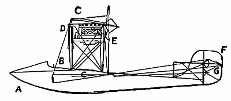
Grahame-White Military Biplane - side view
Once the value of aerial reconnaissance had been proved, France proceeded to the development of a scouting aeroplane; and the need, in such a machine, is that the observer shall have a clear view ahead and below. The construction of machines was, for this reason, modified. The front elevating plane was moved to the rear, where it was fitted in the form of a flap—as in the case of monoplanes—and the pilot and observer placed in a covered-in body, which projected in front of the main-planes, as shown in the figure. By placing the body before the planes, the observer has a clear view ahead and on either side; and even when he leans over the side, and looks directly downward, there is no surface to obstruct him. A. Covered-in body, with seats for pilot and passenger B. Motor (to minimise wind resistance, only the lower cylinders are exposed to the air) C. Propeller D. Main-planes E. Rudder F. Elevator G. Landing gear.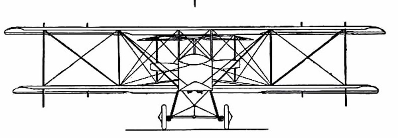
 Of the devices suggested [for man to fly] many showed ingenuity; and some were quaint, in view of ...") Besnier’s Apparatus
Besnier’s Apparatus
Of the devices suggested [for man to fly] many showed ingenuity; and some were quaint, in view of what we know of flight to-day. In the machine, for instance, designed by an experimenter named Besnier—who was a locksmith by trade—there were four lifting planes, closing on the up-stroke and opening on the down, and these the operator was to flap by the use of his hands and feet.") King George IV. in His Pony Phaeton
King George IV. in His Pony Phaeton Of the doings of another of these brave but reckless men—a Saracen who tried to fly in the twelfth...") First attempts
First attempts
Of the doings of another of these brave but reckless men—a Saracen who tried to fly in the twelfth century—there is fuller information. He provided himself with wings which he stiffened with wooden rods, and held out upon either side of his body. Wearing these, he mounted to the top of a tower in Constantinople and stood waiting for a favourable gust of wind. When this came and caught his wings, he “rose into the air like a bird.” And then, of course, seeing that he had no idea of balancing himself when actually aloft, he fell pell-mell and “broke his bones.” People who had gathered to watch, seeing this inglorious ending to the flight, burst into laughter: ridicule rather than praise, indeed, was the fate of the pioneers, even to the days when the first real flights were made. In the launching of gliders, some French experimenters showed ingenuity. The brothers Voisin, for in...") Voisin Glider towed by a motor-car
Voisin Glider towed by a motor-car
In the launching of gliders, some French experimenters showed ingenuity. The brothers Voisin, for instance, who played a prominent part in the early tests in France, adopted the plan illustrated. The gilder was towed by a motor-car across an open stretch of ground; then, when its speed was sufficient for the planes to lift, it rose and flew behind the car like a kite. A.A.—Main-planes; B. Double front elevator; C. Rudder (two narrow vertical planes); D. Motor; E. P...") The Wright Biplane
The Wright Biplane
A.A.—Main-planes; B. Double front elevator; C. Rudder (two narrow vertical planes); D. Motor; E. Propellers; F. Pilot’s lever; G. Skids upon which machine landed. It is now possible to describe, as a completed craft, the Wright power-driven plane; The picture shows its appearance; and in looking at it one is struck by the fact that, save for one or two modifications, and the fitting of motor and propellers, the machine is practically a glider, such as the Wrights used for soaring tests. Of the changes to be observed, the most interesting concern the elevator and rear-rudder. The former, it will be seen, has a double plane; it is, in fact, a smaller biplane on the principle of the main-planes. Needing to increase the surface of the elevator, the brothers fixed one plane above another so as to make the construction stronger and occupy less space. The rear-rudder, acting like that of a ship. (660 visits)") London Hackney Cab (Boulnois’ Patent)
London Hackney Cab (Boulnois’ Patent)") Construction of a Monoplane wing
Construction of a Monoplane wing A. Biplane; B. Rail; C. Rope passing from the aeroplane round the pulley-wheel (D.) and thence to th...") Wright Launching Rail
Wright Launching Rail
A. Biplane; B. Rail; C. Rope passing from the aeroplane round the pulley-wheel (D.) and thence to the derrick (E.); (F.) Falling weight. Details of propulsion and control being arranged, there remained the question of how the machine should be launched into the air. In their gliding tests, it will be remembered, the Wrights employed assistants, who held the machine by the wing-tips and ran forward with it. But the weight of the power-driven machine, and its greater size, prevented such a plan as this. They decided, therefore, to launch it from a rail, and to aid its forward speed, at the moment of taking the air, by a derrick and a falling weight. A form of glider, mounted upon hollow wooden floats—anticipating the sea-plane of to-day—and tow...") Voisin Glider on the river Seine
Voisin Glider on the river Seine
A form of glider, mounted upon hollow wooden floats—anticipating the sea-plane of to-day—and towed upon the river Seine by a motor-boat. This gilder also, when its speed became sufficient, rose into the air. In the construction of the machine, a biplane, one notes resemblances to the method of the Wrights; and yet generally the craft is dissimilar.") Sacramento Electric, Gas and Railway Co., Car 2
Sacramento Electric, Gas and Railway Co., Car 2 Two assistants took the machine by its plane-ends and ran forward with it, the pilot assuming before...") Launching the Wright Glider
Launching the Wright Glider
Two assistants took the machine by its plane-ends and ran forward with it, the pilot assuming beforehand his position upon the plane; then, when they had gained a pace sufficient for the machine to soar, they released their hold and it glided forward. Beneath the glider, under the centre of the lower plane, there were two wooden skates or runners, and these took the weight of the machine when it alighted, and allowed it to slide forward across the ground before coming to rest. By the use of these landing skids, and by steering at as fine an angle as possible, the Wrights found they could touch ground, even at 20 miles an hour and lying across the machine, without injury either to themselves or the craft., 1750 (672 visits)") Travelling Posting Carriage (1), 1750
Travelling Posting Carriage (1), 1750 A ship that was built half a century too early. This huge vessel, built in 1857, was designed to mak...") The Great Eastern
The Great Eastern
A ship that was built half a century too early. This huge vessel, built in 1857, was designed to make the voyage from England to Australia without refuelling. She never made the voyage to Australia, but was used to lay the Atlantic cable. She was ahead of her time, for engines had not developed to the point where she could be properly propelled. Now, patient and assiduous, he (Lilienthal) began to teach himself the art of aerial balance. Raisin...") Lilienthal gliding
Lilienthal gliding
Now, patient and assiduous, he (Lilienthal) began to teach himself the art of aerial balance. Raising his wings to his shoulders he would face the wind—which in his first tests he did not care to be blowing at more than ten or fifteen miles an hour. Then, running against the wind to increase the pressure beneath his wings, he would raise his legs and begin to glide, moving forward and at the same time downward. How he appeared when in flight is indicated by the picture.") Space Shuttle - top plan
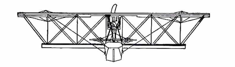
Space Shuttle - top plan showing the shape of wings and tail, and the positions of the pilot and passenger within the hull.
...") A Flying Boat top view
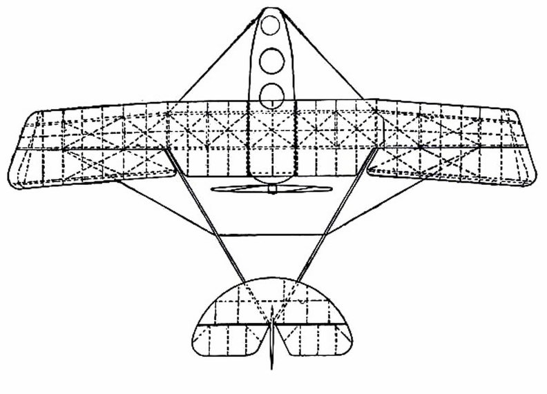
A Flying Boat top view
showing the shape of wings and tail, and the positions of the pilot and passenger within the hull.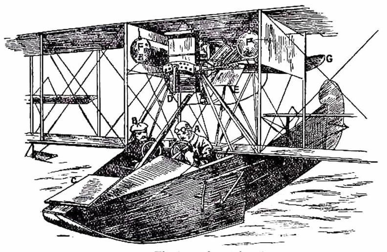
 Da Vinci’s second flyer was a helicopter. An aërial screw 96 feet in diameter was to be turned by...") Da Vinci’s helicopter
Da Vinci’s helicopter
Da Vinci’s second flyer was a helicopter. An aërial screw 96 feet in diameter was to be turned by a strong and nimble artist who might, by prodigious effort, lift himself for a short time. Though various small paper screws were made to ascend in the air, the larger enterprise was never seriously undertaken. Many subsequent inventors developed the same project; but the fellow turning the screw always found it dreadful toil and a hopelessly futile task. Of late the man-driven helicopter has been abandoned, but the motor-driven one is very much cultivated. Scores of inventors in recent years, aided by light motors, have been trying to screw boldly skyward, and some have succeeded in rising on a helicopter carrying one man. This balloon was a truly scientific creation, which advanced aërostation from tottering infancy alm...") Charles’ passenger balloon
Charles’ passenger balloon
This balloon was a truly scientific creation, which advanced aërostation from tottering infancy almost to full prime. The bag was a sphere 27½ feet in diameter made of gores of varnished silk. A net covered the upper half and was fastened to a horizontal hoop girding the middle of the globe, and called the “equator.” From the equator depended ropes which supported, just below the spherical bag, a wicker boat measuring eight feet by four, covered with painted linen and beautifully ornamented. The balloon had at the bottom a silk neck 7 inches in diameter, to admit the gas during inflation, and at the top, a valve which could be opened by means of a cord in the boat to let out gas during a voyage, so as to lower the balloon, or to relieve excessive pressure. In the boat were carried sand ballast to regulate the height of ascension, a barometer to measure the elevation, anchor and rope for landing, a thermometer, notebook, provisions, and all the paraphernalia of a scientific voyage. Barring the fancy boat, this is almost a description of a good modern balloon.") Sacramento Northern Car 64 on C Street
Sacramento Northern Car 64 on C Street The largest hot-air balloon ever constructed, La Flesselle, was launched from the suburbs of the cit...") La Flesselle
La Flesselle
The largest hot-air balloon ever constructed, La Flesselle, was launched from the suburbs of the city of Lyons on January 19, 1784, just two months after the ascent of the first human passengers. It was also one of the most troublesome to assemble and keep in repair. Day by day, for more than a week, the balloon was inflated for the purpose of attaching the ropes to support the great gallery. But the wind blew dreadfully at times; rain and snow fell on the machine; frost and ice covered the huge bag; many rents ensued, demanding frequent repairs. On one occasion, when fed too freely with flame from straw sprinkled with alcohol, the monstrous ship rose so vigorously as to drag fifty men with it some distance along the ground. Finally on the 19th of January, when the weather moderated, the operators built small fires under the scaffold below the balloon, and thawed away the ice from the drenched and frozen bag. Then they stocked its gallery with straw and pitchforks, with fire extinguishers, and other provisions for the journey. The inflation beginning about noon, occupied but seventeen minutes. The balloon swelled out rapidly, with the roaring flames ascending inside, and at last stood forth huge and majestic before the admiring multitude—a towering thing of magic growth, 100 feet in diameter by 130 feet high.") Sacramento City Lines Car 90
Sacramento City Lines Car 90 (Early Type)
A. Elevating-plane
B. Seats for pilot and passenger
C. Main-planes
D. Motor with...") Maurice Farman Biplane
Maurice Farman Biplane
(Early Type) A. Elevating-plane B. Seats for pilot and passenger C. Main-planes D. Motor with two-bladed propeller E. Vertical panel F. Aileron G. Tail-planes H. Rudders I. Landing chassis. By the use of such a machine as this, twenty years hence, we shall be able to spend a week-end in Ne...") Airliners of the future
Airliners of the future
By the use of such a machine as this, twenty years hence, we shall be able to spend a week-end in New York, as we do now in Paris or Scotland. Flying at immense heights, and at speeds of 200 miles an hour, these huge aircraft—carrying hundreds of passengers in vibrationless luxury—will pass from London to New York in less than twenty hours.") P.G. and E Car at Oak Park
P.G. and E Car at Oak Park") Car 42 at N St. Carbarn
Car 42 at N St. Carbarn Apart from governing the ascending or descending movement, there was the question of preventing a ma...") The Wright Wing-warp
The Wright Wing-warp
Apart from governing the ascending or descending movement, there was the question of preventing a machine from slipping sideways; and this the Wrights solved ingeniously. They saw, of course, that when their glider lurched to one side or the other, they would need some power to tilt it back again. So they devised a system by which the plane-ends of their machine—being made flexible—might be warped, or caused to shift up and down. This action the operator controlled, as he lay across the lower plane, by a movement of cords, and its operation is shown in Figure. The effect upon the machine may be described thus: should a wind-gust tilt down one plane-end, the “warp” upon that side of the machine was drawn down also, and the effect of this—seeing that it caused the plane to assume a steeper angle to the air and exercise a greater lift—was to raise the plane-ends that had been driven down by the gust. By a system of connecting the control cords, this balancing influence was made to act with double force; when one wing warped down, the other moved up; and, in this way, while the side of the machine tilted down was made to rise, the other plane-ends, which had been lifted, were made to descend. A dual righting influence was thus obtained. This system, which imitates the flexing movements made by a bird, was an important device; the Wrights patented it—combining the movement with an action of the rudder—and brought cases at law to enforce their rights.") Tandem
Tandem