


 Young woman") Young woman
Young woman
Young woman Woman writing letters at cluttered Victorian desk") Woman writing letters at cluttered Victorian desk
Woman writing letters at cluttered Victorian desk
Woman writing letters at cluttered Victorian desk Do you understand what appropriateness means? It means wearing the suitable kind of clothing for eve...") Which of these girls looks ready to do her work
Which of these girls looks ready to do her work
Do you understand what appropriateness means? It means wearing the suitable kind of clothing for every occasion. It is our duty to be as well dressed as possible, for our friends' sakes as well as for our own; but a well-dressed girl is never conspicuous. Clothes which would be appropriate in a large city for a reception might be very inappropriate in a small town. Our daily clothes should be adapted to our uses, whether in country or city. Would you wear your party dress for gardening or for tennis or skating?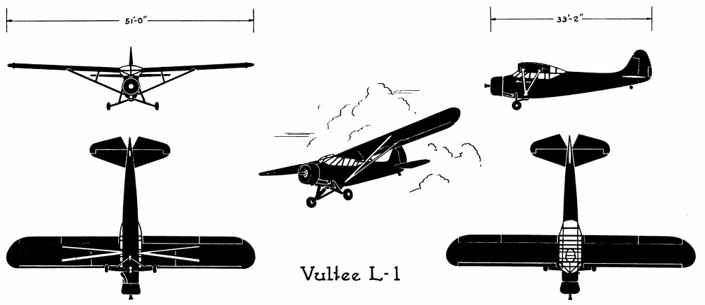 Vultee L-1
Vultee L-1 Front Side Perspective Bottom Top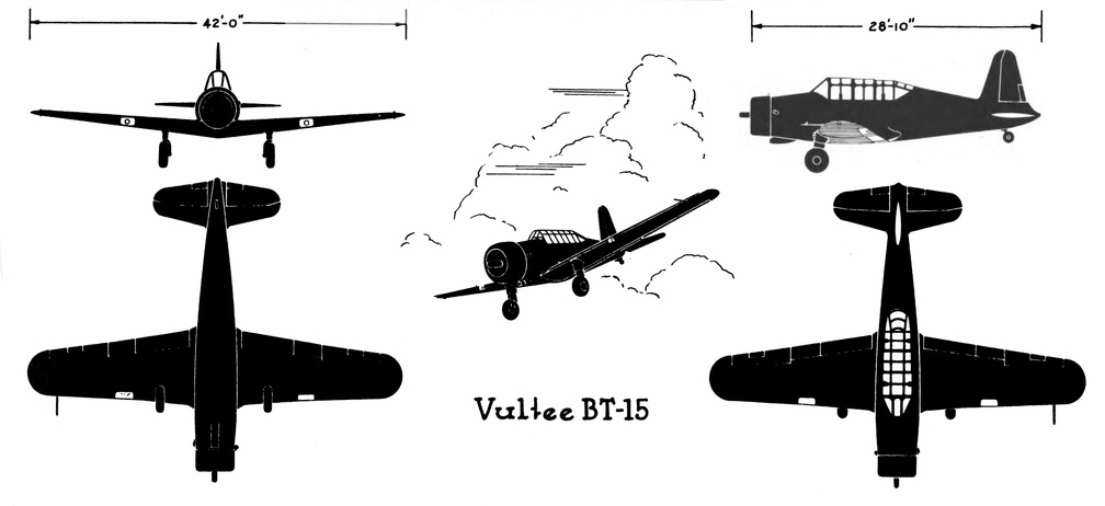 Vultee BT-15
Vultee BT-15 Front Side Perspective Bottom Top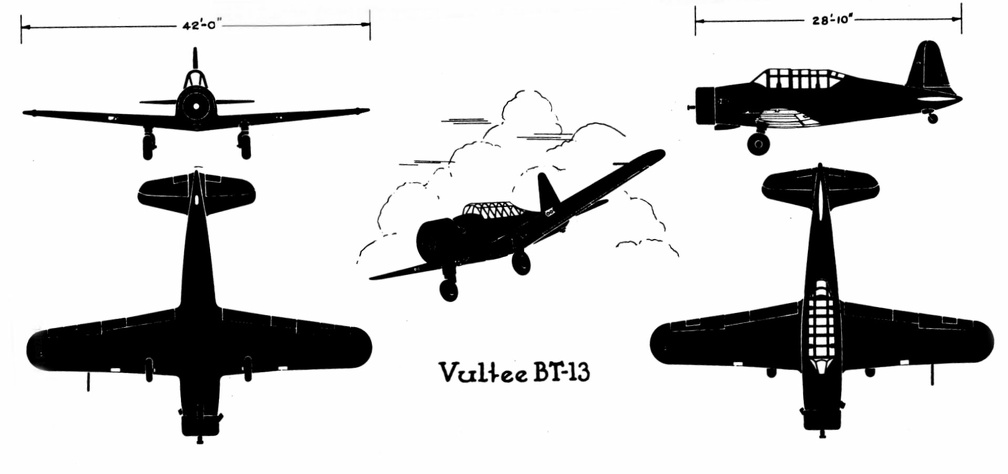 Vultee BT-13
Vultee BT-13 Front Side Perspective Bottom Top Vultee A-31
Front Side
...") Vultee A-31
Vultee A-31
Vultee A-31 Front Side Perspective Bottom Top USEFUL FUR COAT, as sketch, in good Seal Musquash, made from reliable skins, lined new striped chiff...") Useful Fur Coat
Useful Fur Coat
USEFUL FUR COAT, as sketch, in good Seal Musquash, made from reliable skins, lined new striped chiffon taffeta silk. Price 13-½. Gns. Actual value. 19-½ Gns. Would you believe that the pattern of these two dresses is exactly the same? This illustrates how yo...") Two looks - same pattern
Two looks - same pattern
Would you believe that the pattern of these two dresses is exactly the same? This illustrates how you can vary a dress once you find the foundation lines that are becoming to you. One pattern can suffice for both a tailored and an afternoon dress, as you see both effects are pleasing in their slenderness. If you have to take a side road on the right, keep your arm stretched out in horizontal direction o...") Turn Signal
Turn Signal
If you have to take a side road on the right, keep your arm stretched out in horizontal direction outside the car. [Translated online from the Dutch ] There needs to be an equipment of spare machines also; and a number of travelling workshops with ski...") Travelling workshop for the repair of military aeroplanes
Travelling workshop for the repair of military aeroplanes
There needs to be an equipment of spare machines also; and a number of travelling workshops with skilled engineers, which can be rushed from place to place for the repair of damaged craft. A sketch of one of these workshops on wheels, which are vital to the organisation, is seen in the figure Air raid siren in Paris") Tooting the sirens of warning
Tooting the sirens of warning
Air raid siren in Paris Thomas A Edison") Thomas A Edison
Thomas A Edison
Thomas A Edison British plane flying over the trenches in the great war") They swoop down over the trenches
They swoop down over the trenches
British plane flying over the trenches in the great war The Western Front, 1915-18
For a year and a half, until July, 1916, the Western front remained in...") The Western Front, 1915-18
The Western Front, 1915-18
The Western Front, 1915-18 For a year and a half, until July, 1916, the Western front remained in a state of indecisive tension. There were heavy attacks on either side that ended in bloody repulses. The French made costly{v2-517} but glorious thrusts at Arras and in Champagne in 1915, the British at Loos. The Voisin Biplane - top view") The Voisin Biplane - top view
The Voisin Biplane - top view
The Voisin Biplane - top view At the beginning of 1909 there were two types of successful aeroplane—the Wright and the Voisin. B...") The Voisin Biplane
The Voisin Biplane
At the beginning of 1909 there were two types of successful aeroplane—the Wright and the Voisin. Bleriot had flown with his monoplane and flown well; but he was still in the process of evolving a practical machine, and several other inventors were in a similar stage. It was the Wright and the Voisin which had proved their worth; and the Wright, as has been said, was the better of the two. Of the Voisin, as flown in 1909, a reproduction is given in the figure. It was a heavier aeroplane than the Wrights’, owing largely to the weight of its alighting gear (250 lbs.) and of its big balancing tail (more than 100 lbs.); hence the necessity for using a 50-h.p. motor, which drove a two-bladed metal propeller at the rate of 1200 revolutions a minute. The Voisin brothers, and other French makers, did not approve of the two-propeller system of the Wrights: they preferred one screw, revolving at high speed. But there was no doubt—at any rate in this stage of aviation—that the Wright method was more efficient than that of the Frenchmen. It was calculated, indeed, that the Wright biplane, when actually in the air, could be driven at an expenditure of only 15 h.p.; whereas the Voisin, even with its 50-h.p. motor running at full speed, had only just enough power to fly. A. Elevating plane B. Pilot’s seat C.C. Main-planes D. Engine and propeller E. Landing chassis F. Balancing tail G. Rudder. The Turkish Treaty, 1920") The Turkish Treaty, 1920
The Turkish Treaty, 1920
The Turkish Treaty, 1920 The Tube") The Tube
The Tube
The Tube The simple dress skirt and shirt waist") The simple dress skirt and shirt waist
The simple dress skirt and shirt waist
The simple dress skirt and shirt waist The seaplane shoots off the catapult") The seaplane shoots off the catapult
The seaplane shoots off the catapult
The seaplane shoots off the catapult The Savoy") The Savoy
The Savoy
The Savoy An experimenter who braved this apathy and won his way until he became a constructor of aircraft, wa...") The Roe Triplane
The Roe Triplane
An experimenter who braved this apathy and won his way until he became a constructor of aircraft, was Mr. A. V. Roe. For some time he was an advocate of the triplane form of machine—a craft, that is to say, with three main-planes fitted one above another. The machine with which he obtained flights, although they were very brief, is seen in the figure. Subsequently, however, Mr. Roe adopted the biplane form. His distinction in the pioneer days was that he managed to make his triplane lift into the air and fly a short distance, with the aid of a motor-cycle engine developing no more than 9 h.p. A.A.A. Three main-planes B. Motor C. Four-bladed propeller D.D.D. Triplane tail E. Rudder F. Landing gear. The Regent Canal at Maida Hill") The Regent Canal at Maida Hill
The Regent Canal at Maida Hill
The Regent Canal at Maida Hill The Pub") The Pub
The Pub
The Pub The Battle of the Marne shattered the original German plan. For a time France was saved. But the Ger...") The Original German Plan, 1914
The Original German Plan, 1914
The Battle of the Marne shattered the original German plan. For a time France was saved. But the German was not defeated; he had still a great offensive superiority in men and equipment. His fear of the Russian in the east had been relieved by a tremendous victory at Tannenberg. His next phase was a headlong, less elaborately planned campaign to outflank the left of the allied armies and to seize the Channel ports and cut off supplies coming from Britain to France. Both armies extended to the west in a sort of race to the coast. Then the Germans, with a great superiority of guns and equipment, struck at the British round and about Ypres. They came very near to a break through, but the British held them. It is worth while for the reader to compare the treaty maps we give with what we have called the nat...") The Natural Political Map of Europe
The Natural Political Map of Europe
It is worth while for the reader to compare the treaty maps we give with what we have called the natural political map of Europe. The new arrangements do approach this latter more closely than any previous system of boundaries. It may be a necessary preliminary to any satisfactory league of peoples, that each people should first be in something like complete possession of its own household. The Heart of the City") The Heart of the City
The Heart of the City
The Heart of the City The Good Intent - Chelsea") The Good Intent - Chelsea
The Good Intent - Chelsea
The Good Intent - Chelsea The Forth Bridge at the Present Day.
Building the Bridge. ...") The Forth Bridge
The Forth Bridge
The Forth Bridge at the Present Day. Building the Bridge. Train crossing the Bridge. The mouth of the Forth has very nearly bitten Scotland in two, and anybody who wishes to travel from Edinburgh to Dunfermline would have to go a long way round if they objected to crossing the river. Formerly a great many people did object to this, because they knew that, although the voyage was only about a short mile, the great billows from the North Sea would meet them before it was over, and give them a very unpleasant time. So everybody who had anything to do with the Forth was willing that it should be spanned by a reliable bridge, and plans for carrying this into effect were frequently proposed. Indeed, arrangements were almost completed in 1879 for building a huge suspension bridge from shore to shore. The drawings were made, the estimates prepared, and the spades and trowels even beginning to work on the foundations, when, one sad December night, a terrible gale arose. All through the hours of darkness it roared and shrieked across the British Isles, working havoc upon sea and land, but, when morning came at last, few were prepared for the appalling catastrophe it had caused. Sweeping up the Firth of Tay, it had torn away a portion of the great railway bridge that crossed the inlet, and hurled it into the water. A train was passing over at the time, and plunged into the abyss with all its passengers. The terrible event shook public confidence, and we might almost say that the gale of that December night caught all the drawings and papers connected with the proposed suspension bridge over the Forth, and swept them from public favour. Immediately afterwards, Sir John Fowler and Mr. Benjamin Baker (both celebrated engineers) came forward with an alternative plan of which no one could doubt the strength. It may perhaps be described as an arch-suspension bridge, because the design includes the strength of both styles; but engineers themselves call it a cantilever bridge. The depth bomb destroys a U-Boat") The depth bomb destroys a U-Boat
The depth bomb destroys a U-Boat
The depth bomb destroys a U-Boat Of famous aeroplanes at Rheims, five types stood out by themselves—the Farman, the Voisin, the Wri...") The Curtiss Biplane
The Curtiss Biplane
Of famous aeroplanes at Rheims, five types stood out by themselves—the Farman, the Voisin, the Wright, the Bleriot, and the Antoinette, all of which have been described. But there was one other, which few people had heard of before it appeared here. This was the Curtiss biplane, built by an American named Glenn H. Curtiss, and engined with a motor which also bore his name. Curtiss had experimented with many power-driven machines—motor-cycles, motor-cars, airships, and aeroplanes—and had won a prize in America with a small, light biplane, and it was a craft of this type—as seen in the figure —that he brought with him to Rheims, his idea being to compete for the speed prize. The machine had a front elevator and tail-planes, according to the practice in biplane construction; but an innovation was the setting of the ailerons midway between the main-planes—a position that will be noted in the sketch; another novelty was the way these ailerons operated. At the pilot’s back, as he sat in his driving seat, was an upright rod with two shoulder-pieces—by means of which, should he shift his body, he could swing the rod from side to side. Wires ran from the rod to the ailerons; and if the pilot leaned over, say, to the right, he drew down the ailerons on the left side of the machine. The merit of such a control was that it was instinctive; that is to say, should the biplane tip down on one side, it was natural for the pilot to lean away from the plane-ends that were sinking; and he operated the ailerons automatically, as he did this, and so brought the machine level again. A. Elevating-planes B. Pilot’s seat and control-wheel C.C. Main-planes D. Ailerons E. Motor and propeller F. Tail-plane and rudder. showing the large size of the elevators, the position of the pilot, and the placing of the propeller...") The Cody Biplane from above
The Cody Biplane from above
showing the large size of the elevators, the position of the pilot, and the placing of the propellers. Another ardent worker in England, and one destined to become famous, was Mr. S. F. Cody. After devel...") The Cody Biplane
The Cody Biplane
Another ardent worker in England, and one destined to become famous, was Mr. S. F. Cody. After developing a system of man-lifting kites which the British War Office acquired, he joined the military aircraft factory that had been established at Farnborough. Here, after tests with dirigible balloons, he began the construction of experimental biplanes—all machines of large size. Early in 1909 he made brief flights—the longest being one of about 250 yards. Then, after alterations to his machine, he managed in July to fly a distance of 4 miles. This he increased afterwards to 8 miles; and then on 1st September flew for 1 hour 3 minutes, rising to a height of 300 feet. Cody’s biplane was a very large machine, having 1000 square feet of lifting surface—twice that of the Farman or Voisin. Driving it was an 80-h.p. engine, which operated two propellers on the system used by the Wrights. With its pilot on board the machine weighed 2170 lbs. A. Elevating-planes and vertical-plane B. Pilot’s control lever C.C. Main-planes D. Motor E. Propellers F. Rudder G. Landing gear H. Rear skid. Airing clothing
The body must be kept clean; and clothing worn next to it should also be kept cle...") The clothing worn during the day should be aired at night
The clothing worn during the day should be aired at night
Airing clothing The body must be kept clean; and clothing worn next to it should also be kept clean at night as well as during the day. Who can remember how many pints of water the normal body gives off each day? It loses about three pints in 24 hours. Can you recall what becomes of this waste? Yes, some is evaporated, but some is collected by our clothes; that is why they are soiled as they collect the perspiration and excretions, although often they do not look soiled. The day garments should be hung up at night in a place where they will air and dry out by morning. The Chelsea Arts Ball") The Chelsea Arts Ball
The Chelsea Arts Ball
The Chelsea Arts Ball The bloomers and middy blouse") The bloomers and middy blouse
The bloomers and middy blouse
The bloomers and middy blouse The Bleriot Monoplane - top view showing its bird-like shape and the position of the pilot.") The Bleriot Monoplane - top view
The Bleriot Monoplane - top view
The Bleriot Monoplane - top view showing its bird-like shape and the position of the pilot. A. Propeller
B. Motor
C. Sustaining-plane
D. Pilot’s seat
E. Landing chassis
F. Combined tail...") The Bleriot Monoplane
The Bleriot Monoplane
A. Propeller B. Motor C. Sustaining-plane D. Pilot’s seat E. Landing chassis F. Combined tail and elevating-planes G. Rudder. showing the spread of the planes and tail, and the delicate taper of the long, canoe-shaped body.") The Antoinette Monoplane - top view
The Antoinette Monoplane - top view
showing the spread of the planes and tail, and the delicate taper of the long, canoe-shaped body. At the beginning of 1909 a new monoplane made its appearance in France—a powerful, finely construc...") The Antoinette Monoplane
The Antoinette Monoplane
At the beginning of 1909 a new monoplane made its appearance in France—a powerful, finely constructed, and very stable machine. It was the Antoinette, designed by a famous engineer, and it was this craft which interested Latham. M. Levavasseur was the designer of it and of a specially lightened motor, first applied to motor-boats, and afterwards to the experimental biplane of M. Santos-Dumont and also to the aeroplane with which Farman first flew. The Antoinette, which M. Levavasseur also fitted with one of his motors, was a large monoplane—far larger than the Bleriot; and built not with the idea of being a fair-weather machine, but to fly in winds. The span of its wings was 46 feet, and they contained 365 square feet of sustaining surface, while the total weight was 1040 lbs. A. Propeller B. Motor C. Sustaining-plane D. Pilot’s seat and controlling wheel E.E. Vertical rudders F. Elevating-plane G. Landing gear. Swerving at intersections") Swerving at intersections
Swerving at intersections
Swerving at intersections With an open torpedo, the stop signal can also be given by sticking the arm straight up. In any case...") Stop Signal
Stop Signal
With an open torpedo, the stop signal can also be given by sticking the arm straight up. In any case, account must then be taken of the somewhat higher rear of the car, or of the possibility that the passengers behind are masking the movement of the arm. [Translated online from the Dutch ] Stearman PT-17 & 18
Front ...") Stearman PT-17 &18
Stearman PT-17 &18
Stearman PT-17 & 18 Front Side Perspective Bottom Top A machine that has achieved success, owing to its power of varying speed, is the Sopwith military bi...") Sopwith Military Biplane
Sopwith Military Biplane
A machine that has achieved success, owing to its power of varying speed, is the Sopwith military biplane. Adopting a practice that has become general, its wings are fitted upon what is practically a monoplane body. Tail-planes and rudder are the same as in a monoplane. The top main-plane, as will be seen, is set slightly in advance of the lower. The system is called “staggering”; and the idea is that, by placing the upper plane ahead of the lower, the total lifting power will be increased. It has been proved a disadvantage of the biplane that, when the main-planes are placed one above another, there is a slight loss of lift owing to the fact that, acting upon the air as they do quite close to each other, a certain amount of interference occurs between them—one tending to disturb the air-stream in which the other moves. By “staggering” the two planes this interference is overcome; but some makers regard it as a small consideration, and build their planes in the ordinary way, allowing as large a gap as possible between them. In the Sopwith military machine, engine and propeller are in front of the main-planes; then come the places for pilot and observer. The pilot sits first, and the body of the machine is so high that only his head appears above it, while just in front of his face, to deflect the wind-rush from the propeller, there is a raised section of the hull which acts as a screen. Behind the pilot, sitting in a second opening in the hull, is the observer. He has a view forward, rendered the better by setting back the lower-plane; while at the point at which it joins the body of the machine, immediately below him, this plane is hollowed out, so that he can look directly upon the earth below. Small windows are also fitted upon either side of the hull. Through those in front the pilot may glance when descending from a flight, so as to judge his distance from the ground, while the others are utilised by the observer, as he turns to look from side to side. This biplane, and many others, is balanced against sideway roll by ailerons, and not by warping the wings. Constant warping, such as is necessary in the everyday use of machines, has been declared to strain a plane and render it weak; therefore the use of ailerons is now favoured. A. Propeller B. Motor, partly hidden by shield C.C. Main-planes D. Pilot’s seat E. Observer’s seat F. Outlook windows in side of hull G. Rudder H. Elevating-plane I. Landing gear. Some types of American and foreign aeroplanes") Some types of American and foreign aeroplanes
Some types of American and foreign aeroplanes
Some types of American and foreign aeroplanes Some types of American and foreign aeroplanes") Some types of American and foreign aeroplanes
Some types of American and foreign aeroplanes
Some types of American and foreign aeroplanes Soho Market") Soho Market
Soho Market
Soho Market Sighting through the pantel, the gunner positions the aiming post by extending his left hand.") Sighting the M102 Howitzer
Sighting the M102 Howitzer
Sighting through the pantel, the gunner positions the aiming post by extending his left hand. Shopping") Shopping
Shopping
Shopping Shop engine, 1901") Shop engine, 1901
Shop engine, 1901
Shop engine, 1901 Ships the British, and the German, navy might have had! Designs by the Kaiser and other naval theori...") Ships the British, and the German, navy might have had
Ships the British, and the German, navy might have had
Ships the British, and the German, navy might have had! Designs by the Kaiser and other naval theorists. The first illustration on this page is a design for a battle-ship made by the Kaiser in 1893, to replace the old "Preussen," then out of date. The vessel was to carry four large barbettes and a huge umbrella-like fighting-top. Illustration No. 2 is an Immersible Ironclad, designed by a French engineer named Le Grand, in 1862. In action the vessel was to be partly submerged, so that only her three turrets and the top of the armoured glacis would be visible. No. 3 is Admiral Elliott's "Ram," of 1884. The ship was to carry a "crinoline" of stanchions along her water-line, practically a fixed torpedo-net. No. 4 is Thomas Cornish's Invulnerable Ironclad, of 1885. She was to have two separate parallel hulls under water; above she was of turtle-back shape. Ships the British navy might have had! Freaks of marine architecture that have not been officially a...") Ships the British navy might have had
Ships the British navy might have had
Ships the British navy might have had! Freaks of marine architecture that have not been officially adopted. We illustrate here some curious designs for war-ships by various inventors. No. 1 is McDougal's Armoured Whale-back, with conning-towers, a design of 1892 for converting whalebacks into war-vessels. No. 2 is an American design of 1892, Commodore Folger's Dynamite Ram, cigar-shaped, with two guns throwing masses of dynamite or aerial torpedoes. No. 3 is a design by the Earl of Mayo in 1894 and called "Aries the Ram," built round an immense beam of steel terminating in a sharp point, No. 4 is Gathmann's boat for a heavy gun forward, designed in 1900. She was to be of great speed, and the forward gun was to throw 600 lb. of gun-cotton at the rate of 2000 feet per second. A formidable Armada this, had it been practicable. Ship saved by life line thrown from a rescue airship
[Not sure what it did to save the boat]") Ship saved by life line thrown from a rescue airship
Ship saved by life line thrown from a rescue airship
Ship saved by life line thrown from a rescue airship [Not sure what it did to save the boat] Shepherd's Market") Shepherd's Market
Shepherd's Market
Shepherd's Market A coastal sea-plane, as now planned, is a craft having, say, two engines, each devolving 120 h.p., w...") Sea-plane to carry a crew of seven
Sea-plane to carry a crew of seven
A coastal sea-plane, as now planned, is a craft having, say, two engines, each devolving 120 h.p., with a wing span of some 80 feet, and an accommodation in its hull for three men—the pilot, a combatant with a machine-gun, and an observer with an installation of wireless. But types are changing constantly, and the tendency is to build larger craft. A machine weighing a couple of tons is shown, and a novelty in regard to it is that it has wheels upon either side of its boat-shaped car, upon which it can move on land, and which fold upward when it rests upon the water. A. Hull upon which the machine floats when in the sea B.B.B. Wheels upon which it may move when on land, and which fold upward when it is on the water C. Pilot’s controlling wheel D.D. Main sustaining planes E. Four-bladed propeller driven by chain-gearing from engine within the hull. (1420 visits) Scouting over the ruined region between the lines (no man’s land)") Scouting over the ruined region between the lines (no man’s land)
Scouting over the ruined region between the lines (no man’s land)
Scouting over the ruined region between the lines (no man’s land) To meet the demand for a purely scouting machine, in which pilot and passenger shall have a clear fi...") Scouting Monoplane, with occupants below the wings.
Scouting Monoplane, with occupants below the wings.
To meet the demand for a purely scouting machine, in which pilot and passenger shall have a clear field for observation, both above and below, a monoplane has been designed which is called the “parasol.” This machine, a Morane-Saulnier, is shown. The two sustaining wings, forming a single surface, are raised above the body so that its occupants have nothing to impede their view earthward; and they can also see above them—an advantage of course in time of war, seeing that an enemy might be hovering overhead A. Engine and propeller B. Plane raised above hull C. Seats for pilot and passenger D. Rudder E. Elevating-plane. When petrol engines became available, they gave an impetus to the building of airships; for, like th...") Santos-Dumont’s Airship
Santos-Dumont’s Airship
When petrol engines became available, they gave an impetus to the building of airships; for, like the aeroplane, the airship needed a motive agent which gives a high power for a low weight. One of the first to use a petrol motor in an airship with success was M. Santos-Dumont, whose name has been mentioned in connection with aeroplanes. He tested small, light airships, driven by petrol engines and two-bladed propellers—as illustrated in figure; and with one of these, on a calm, still day, he flew over Paris and round the Eiffel Tower. A. Gas envelope B. Wheeled framework which carried motor, propeller, and pilot’s seat C. Elevating-plane D. Horizontal rear-plane E. Rudder. Ryan PT-22
Front Side
...") Ryan PT-22
Ryan PT-22
Ryan PT-22 Front Side Perspective Bottom Top